

Question: Consider the diff-amp shown in Figure P11.62. The circuit parameters are (V^{+}=3 mathrm{~V}, V^{-}=-3 mathrm{~V}), and (I_{Q}=0.4 mathrm{~mA}). The npn transistor parameters are (beta_{mathrm{npn}}=180, V_{B
Consider the diff-amp shown in Figure P11.62. The circuit parameters are \(V^{+}=3 \mathrm{~V}, V^{-}=-3 \mathrm{~V}\), and \(I_{Q}=0.4 \mathrm{~mA}\). The npn transistor parameters are \(\beta_{\mathrm{npn}}=180, V_{B E}\) (on) \(=0.7 \mathrm{~V}\), and \(V_{A N}=120 \mathrm{~V}\), and the pnp transistor parameters are \(\beta_{\mathrm{pnp}}=120, V_{E B}(\mathrm{on})=0.7 \mathrm{~V}\), and \(V_{A P}=80 \mathrm{~V}\).
(a) Sketch the small-signal equivalent circuit for the diff-amp assuming an ideal differential-mode input signal.
(b) Determine the one-sided differential-mode gain \(A_{d 1}=\Delta v_{O 1} / v_{d}\).
(c) Determine the one-sided differentialmode gain \(A_{d 2}=\Delta v_{O 2} / v_{d}\).
(d) Find the two-sided differential-mode gain \(A_{d 3}=\Delta\left(v_{O 2}-v_{O 1}\right) / v_{d}\).
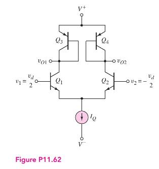
=2 V+ Q3 -0102 Figure P11.62 Vd - = -0112=-2
Step by Step Solution
There are 3 Steps involved in it

Get step-by-step solutions from verified subject matter experts