

Question: The current source to be designed has the general configuration shown in Figure 10.17. The bias voltages are (V^{+}=2.5 mathrm{~V}) and (V^{-}=-2.5 mathrm{~V}). The bias
The current source to be designed has the general configuration shown in Figure 10.17. The bias voltages are \(V^{+}=2.5 \mathrm{~V}\) and \(V^{-}=-2.5 \mathrm{~V}\). The bias current is to be \(I_{O}=80 \mu \mathrm{A}\) and \(V_{D S 2}(\mathrm{sat})=0.5 \mathrm{~V}\). The total power dissipated in the circuit is to be limited to \(1 \mathrm{~mW}\). Use appropriate transistor parameters.
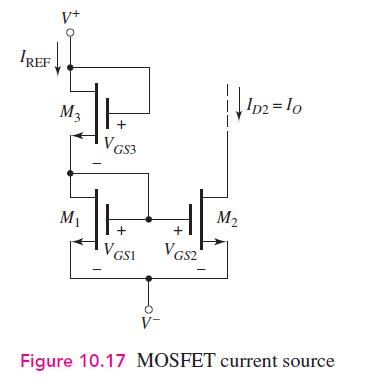
IREF V+ M3 H VGS3 + ||102-10 M M2 + + VGSI VGS2 Figure 10.17 MOSFET current source
Step by Step Solution
There are 3 Steps involved in it
1 Expert Approved Answer
Step: 1 Unlock

Question Has Been Solved by an Expert!
Get step-by-step solutions from verified subject matter experts
Step: 2 Unlock
Step: 3 Unlock