

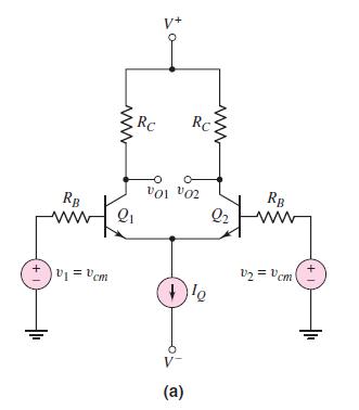
The differential amplifier in Figure 11.51 (a) has the same circuit and transistor parameters as described in
Question:
The differential amplifier in Figure 11.51 (a) has the same circuit and transistor parameters as described in Problem 11.94. The equivalent impedance of the current source is \(R_{o}=10 \mathrm{M} \Omega\) and \(C_{o}=0.4 \mathrm{pF}\).
(a) Determine the frequency of the zero in the common-mode gain.
(b) Find the frequency of the pole in the common-mode gain.
Data From Problem 11.94:-
Consider the differential amplifier in Figure 11.50 (a) with parameters \(I_{Q}=0.8 \mathrm{~mA}, R_{C}=10 \mathrm{k} \Omega\), and \(R_{B}=0.5 \mathrm{k} \Omega\). The transistor parameters are \(\beta=150, V_{B E}\) (on) \(=0.7 \mathrm{~V}, V_{A}=\infty, C_{\pi}=1.2 \mathrm{pF}\), and \(C_{\mu}=0.2 \mathrm{pF}\).
(a) Determine the low-frequency differential-mode gain \(A_{d}=v_{o 2} / v_{d}\).
(b) Find the equivalent Miller capacitance of each transistor.
(c) Determine the upper \(3 \mathrm{~dB}\) frequency.
Figure 11.50(a):-
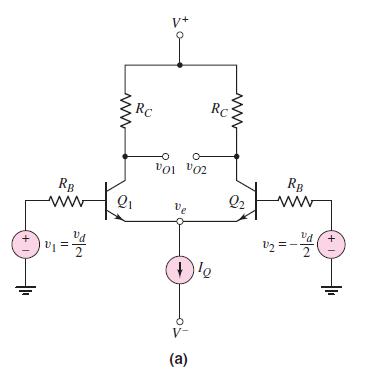
Figure 11.51(a):-
Step by Step Answer:


Microelectronics Circuit Analysis And Design
ISBN: 9780071289474
4th Edition
Authors: Donald A. Neamen
