

Question: 1270 Consider the gain plot in Figure P1270. The goal is to design a circuit that will result in the dashed curve shown on the
12–70 Consider the gain plot in Figure P12–70. The goal is to design a circuit that will result in the dashed curve shown on the plot.
(a) Find the transfer function corresponding to the straightline gain plot.
(b) Use MATLAB to plot the Bode magnitude of the transfer function.
(c) Adjust the poles so that the transfer function results in the dashed line. (Hint: Multiply the two poles into a quadratic expression. Then adjust the Q of the circuit to attain the desired result.)
(d) Design a circuit that will realize the transfer function found in part (c).
(e) Use Multisim to verify your circuit design
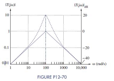
10 0.1 IT (joo)! 10 IT(jw)ldB 20 20 1 0 -20 -40 LICH co (rad/s) 1 10 100 1000 10,000 FIGURE P12-70
Step by Step Solution
There are 3 Steps involved in it

Get step-by-step solutions from verified subject matter experts