

(a) Draw the free-body diagrams for the rotational mechanical system shown below (Figure 2.52). (b) Explain why...
Question:
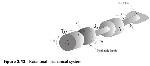
(a) Draw the free-body diagrams for the rotational mechanical system shown below (Figure 2.52).
(b) Explain why the state-variable vector should be chosen as
\[\mathbf{x}(t)=\left[\begin{array}{llll}\theta_{1} & \theta_{3} & \omega_{1} & \omega_{2}\end{array}ight]^{T}\]
(c) Express the dynamic equations in the State-Variable Matrix model (i.e. obtain \(A, B, C, D\) ) where the input is the applied torque \(T(t)\) and the output is the viscous frictional torque on disk \(J_{2}\).
Fantastic news! We've Found the answer you've been seeking!
Step by Step Answer:
a The freebody diagrams are given by b There are four ind...View the full answer

Answered By
Michael Owens
I am a competent Software Engineer with sufficient experience in web applications development using the following programming languages:-
HTML5, CSS3, PHP, JAVASCRIPT, TYPESCRIPT AND SQL.
1+ Reviews
10+ Question Solved
Related Book For 
Design And Analysis Of Control Systems Driving The Fourth Industrial Revolution
ISBN: 9781032718804
2nd Edition
Authors: Arthur G O Mutambara
Question Posted:
