

Question: Consider the pneumatic system in Example 7.2. Construct a Simulink block diagram to find the pressure inside the container, (p(t)), which is assumed to be
Consider the pneumatic system in Example 7.2. Construct a Simulink block diagram to find the pressure inside the container, \(p(t)\), which is assumed to be \(0 \mathrm{~Pa}\) initially. The pressure at the inlet is assumed to be \(101.325 \mathrm{kPa}\).
Data From Example 7.2:
Dry air at a constant temperature of \(20^{\circ} \mathrm{C}(293 \mathrm{~K})\) passes through a valve into a rigid cubic container of \(1 \mathrm{~m}\) on each side (Figure 7.2). The pressure \(p_{\mathrm{i}}\) at the inlet of the valve is constant, and it is greater than \(p\). The valve resistance is approximately linear, and \(R=1000 \mathrm{~Pa} \cdot \mathrm{s} / \mathrm{kg}\). Assume that the filling process is isothermal. Develop a mathematical model of the pressure \(p\) in the container.
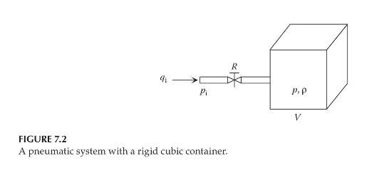
Pi P.P FIGURE 7.2 A pneumatic system with a rigid cubic container. V
Step by Step Solution
3.38 Rating (157 Votes )
There are 3 Steps involved in it

Get step-by-step solutions from verified subject matter experts