

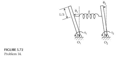
Question: Repeat Problem 13 for the system shown in Figure 5.72, in which each pendulum is a uniform slender rod of mass (m) and length (L).
Repeat Problem 13 for the system shown in Figure 5.72, in which each pendulum is a uniform slender rod of mass \(m\) and length \(L\). The inputs are the torques \(\tau_{1}\) and \(\tau_{2}\) applied to the pivots \(\mathrm{O}_{1}\) and \(\mathrm{O}_{2}\), respectively. When \(\theta_{1}=0, \theta_{2}=0, \tau_{1}=0\), and \(\tau_{2}=0\), the spring is at its free length.
Data From Problem 13:
Consider the two-degree-of-freedom system shown in Figure 5.71, in which two simple inverted pendulums are connected by a translational spring of stiffness \(k\). Each pendulum consists of a point mass \(m\) concentrated at the tip of a massless rope of length \(L . \theta_{1}\) and \(\theta_{2}\) are the angular displacements of the pendulums. When \(\theta_{1}=0\) and \(\theta_{2}=0\), the spring is at its free length.
a. Draw the necessary free-body diagrams and derive the differential equations of motion. Assume small angles for \(\theta_{1}\) and \(\theta_{2}\). Provide the equations in the second-order matrix form.
b. Using the differential equations obtained in Part (a), determine the state-space representation with the angular velocities \(\dot{\theta}_{1}\) and \(\dot{\theta}_{2}\) as the outputs.
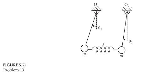
FIGURE 5.72 Problem 14. L/3
Step by Step Solution
3.42 Rating (155 Votes )
There are 3 Steps involved in it

Get step-by-step solutions from verified subject matter experts