

Question: Using the bus impedance matrices determined in Problem 9.51. Problem 9.51 Compute the (5 times 5) per-unit zero-, positive-, and negative-sequence bus impedance matrices for
Using the bus impedance matrices determined in Problem 9.51.
Problem 9.51
Compute the \(5 \times 5\) per-unit zero-, positive-, and negative-sequence bus impedance matrices for the power system given in Problem 9.8. Use a base of 100 MVA and \(15 \mathrm{kV}\) in the zone of generator G2.
Problem 9.8
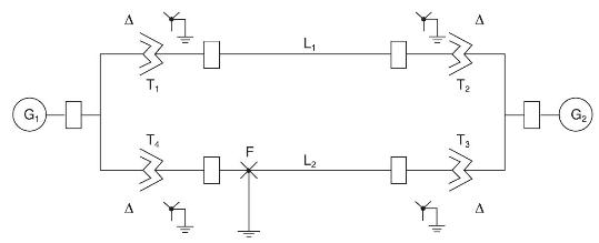
Equipment ratings for the five-bus power system shown in Figure 7.15 are given as follows:
Generator G1: \(\quad 50 \mathrm{MVA}, 12 \mathrm{kV}, \mathrm{X}_{d}^{\prime \prime}=\mathrm{X}_{2}=0.20, \mathrm{X}_{0}=0.10\) per unit
Generator G2: \(\quad 100 \mathrm{MVA}, 15 \mathrm{kV}, \mathrm{X}_{d}^{\prime \prime}=0.2, \mathrm{X}_{2}=0.23, \mathrm{X}_{0}=0.1\) per unit
Transformer T1: \(50 \mathrm{MVA}, 10 \mathrm{kV}\) Y/138 kV Y, X \(=0.10\) per unit
Transformer T2: \(100 \mathrm{MVA}, 15 \mathrm{kV} \Delta / 138 \mathrm{kV} \mathrm{Y}, \mathrm{X}=0.10\) per unit
Each 138-kV line: \(X_{1}=40\) ohms, \(X_{0}=100\) ohms
Draw the zero-, positive-, and negative-sequence reactance diagrams using a \(100-\) MVA, \(15-\mathrm{kV}\) base in the zone of generator G2. Neglect \(\Delta-\mathrm{Y}\) transformer phase shifts.
T F L L T3 A A G
Step by Step Solution
3.31 Rating (148 Votes )
There are 3 Steps involved in it

Get step-by-step solutions from verified subject matter experts