

Question: A Equivalent T-Circuit Transformer Model The transformer model shown in Figure 15-17 can also be modeled using an Equivalent T-Circuit as shown in Figure P15=
A Equivalent T-Circuit Transformer Model The transformer model shown in Figure 15-17 can also be modeled using an Equivalent T-Circuit as shown in Figure P15= 35 . The three inductors are related to the transformer inductances as follows:
\[
\begin{aligned}
& L_{\mathrm{A}}=L_{1} \mp M \\
& L_{\mathrm{B}}=L_{2} \mp M \\
& L_{\mathrm{C}}= \pm M
\end{aligned}
\]
where the upper sign applies for additive coupling and the lower sign for subtractive coupling. Solve Example 15-10 using the Equivalent T-Circuit and Multisim. Compare your results with those in the example.
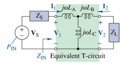
PIN +1 Zs Vs I jOLA JOLB m m + + joLc V ZL ZIN Equivalent T-circuit
Step by Step Solution
3.48 Rating (155 Votes )
There are 3 Steps involved in it

Get step-by-step solutions from verified subject matter experts