

Consider the oneline diagram of a simple power system shown in Figure 9.20. System data in per-unit
Question:
Consider the oneline diagram of a simple power system shown in Figure 9.20. System data in per-unit on a 100-MVA base are given as follows:
Synchronous generators:
G1 & 100 MVA & \(20 \mathrm{kV}\) & \(\mathrm{X}_{1}=\mathrm{X}_{2}=0.15\) & \(\mathrm{X}_{0}=0.05\)
G2 & \(100 \mathrm{MVA}\) & \(20 \mathrm{kV}\) & \(\mathrm{X}_{1}=\mathrm{X}_{2}=0.15\) & \(\mathrm{X}_{0}=0.05\)
Transformers:
\(\begin{array}{llll}\text { T1 } & 100 \text { MVA } & 20 / 220 \mathrm{kV} & \mathrm{X}_{1}=\mathrm{X}_{2}=\mathrm{X}_{0}=0.1 \\ \text { T2 } & 100 \text { MVA } & 20 / 220 \mathrm{kV} & \mathrm{X}_{1}=\mathrm{X}_{2}=\mathrm{X}_{0}=0.1\end{array}\)
Transmission lines:
L12 & \(100 \mathrm{MVA}\) & \(220 \mathrm{kV}\) & \(\mathrm{X}_{1}=\mathrm{X}_{2}=0.125\) & \(\mathrm{X}_{0}=0.3\)
L13 & \(100 \mathrm{MVA}\) & \(220 \mathrm{kV}\) & \(\mathrm{X}_{1}=\mathrm{X}_{2}=0.15\) & \(\mathrm{X}_{0}=0.35\)
L23 & \(100 \mathrm{MVA}\) & \(220 \mathrm{kV}\) & \(\mathrm{X}_{1}=\mathrm{X}_{2}=0.25\) & \(\mathrm{X}_{0}=0.7125\)
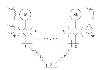
The neutral of each generator is grounded through a current-limiting reactor of 0.08333 per unit on a 100-MVA base. All transformer neutrals are solidly grounded. The generators are operating no-load at their rated voltages and rated frequency with their EMFs in phase. Determine the fault current for a balanced three-phase fault at bus 3 through a fault impedance \(Z_{\mathrm{F}}=0.1\) per unit on a \(100-\mathrm{MVA}\) base. Neglect \(\Delta-\mathrm{Y}\) phase shifts.
Step by Step Answer:


Power System Analysis And Design
ISBN: 9781305632134
6th Edition
Authors: J. Duncan Glover, Thomas Overbye, Mulukutla S. Sarma
