

Question: Equipment ratings and per-unit reactances for the system shown in Figure 9.19 are given as follows: Synchronous generators: (begin{array}{lllll}text { G1 } & 100 text
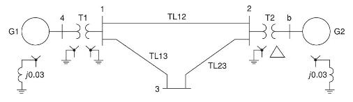
Equipment ratings and per-unit reactances for the system shown in Figure 9.19 are given as follows:
Synchronous generators:
\(\begin{array}{lllll}\text { G1 } & 100 \text { MVA } & 25 \mathrm{kV} & \mathrm{X}_{1}=\mathrm{X}_{2}=0.2 & \mathrm{X}_{0}=0.05 \\ \text { G2 } & 100 \mathrm{MVA} & 13.8 \mathrm{kV} & \mathrm{X}_{1}=\mathrm{X}_{2}=0.2 & \mathrm{X}_{0}=0.05\end{array}\)
Transformers:
\(\begin{array}{llll}\text { T1 } & 100 \text { MVA } & 25 / 230 \mathrm{kV} & \mathrm{X}_{1}=\mathrm{X}_{2}=\mathrm{X}_{0}=0.05 \\ \text { T2 } & 100 \mathrm{MVA} & 13.8 / 230 \mathrm{kV} & \mathrm{X}_{1}=\mathrm{X}_{2}=\mathrm{X}_{0}=0.05\end{array}\)
Transmission lines:
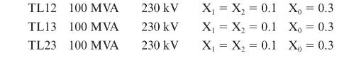
Using a 100-MVA, \(230-\mathrm{kV}\) base for the transmission lines, draw the perunit sequence networks and reduce them to their Thévenin equivalents, "looking in" at bus 3. Neglect \(\Delta-Y\) phase shifts. Compute the fault currents for a bolted three-phase fault at bus 3 .
4 T1 OH G1 j0.03 1 TL13 2 3 TL12 TL23 2 4 T2 b O j0.03 G2
Step by Step Solution
There are 3 Steps involved in it

Get step-by-step solutions from verified subject matter experts