

Question: Consider the system shown in Figure 9.18. (a) As viewed from the fault at (F), determine the Thvenin equivalent of each sequence network. Neglect (Delta-Y)
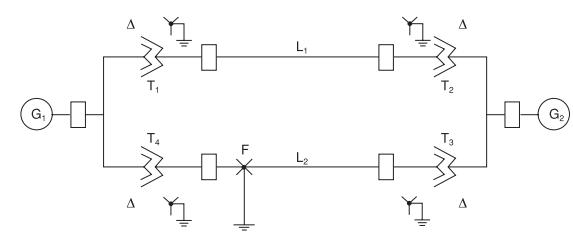
Consider the system shown in Figure 9.18.
(a) As viewed from the fault at \(F\), determine the Thévenin equivalent of each sequence network. Neglect \(\Delta-Y\) phase shifts.
(b) Compute the fault currents for a balanced threephase fault at fault point \(\mathrm{F}\) through three fault impedances \(Z_{\mathrm{FA}}=Z_{\mathrm{FB}}=\) (Z_{\mathrm{FC}}=j 0.5 \) per unit. Equipment data in per-unit on the same base are given as follows:
Synchronous generators:
G1 \(\mathrm{X}_{1}=0.2\)
\(\mathrm{X}_{2}=0.12\)
\(\mathrm{X}_{0}=0.06\)
G2 \(\quad \mathrm{X}_{1}=0.33\)
\(\mathrm{X}_{2}=0.22\)
\(\mathrm{X}_{0}=0.066\)
Transformers:
T1 \(\quad \mathrm{X}_{1}=\mathrm{X}_{2}=\mathrm{X}_{0}=0.2\)
T2 \(\quad \mathrm{X}_{1}=\mathrm{X}_{2}=\mathrm{X}_{0}=0.225\)
T3 \(\quad \mathrm{X}_{1}=\mathrm{X}_{2}=\mathrm{X}_{0}=0.27\)
T4 \(\quad \mathrm{X}_{1}=\mathrm{X}_{2}=\mathrm{X}_{0}=0.16\)
Transmission lines:
\(\begin{array}{lll}\text { L1 } & \mathrm{X}_{1}=\mathrm{X}_{2}=0.14 & \mathrm{X}_{0}=0.3 \\ \text { L1 } & \mathrm{X}_{1}=\mathrm{X}_{2}=0.35 & \mathrm{X}_{0}=0.6\end{array}\)
Figure 9.18
G F L L T HIG
Step by Step Solution
3.44 Rating (160 Votes )
There are 3 Steps involved in it

Get step-by-step solutions from verified subject matter experts