

Question: Draw the per-unit equivalent circuit for the transformers shown in Figure 3.34. Include ideal phase-shifting transformers showing phase shifts determined in Problem 3.32. Assume that
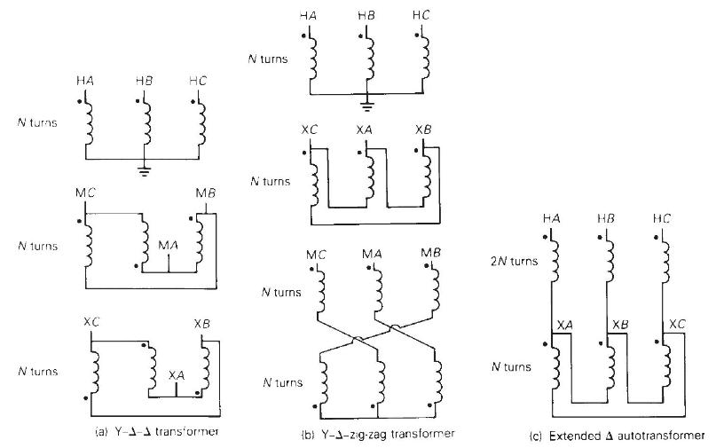
Draw the per-unit equivalent circuit for the transformers shown in Figure 3.34. Include ideal phase-shifting transformers showing phase shifts determined in Problem 3.32. Assume that all windings have the same \(\mathrm{kVA}\) rating and that the equivalent leakage reactance of any two windings with the third winding open is 0.10 per unit. Neglect the exciting admittance.
Figure 3.34
Problem 3.32
Determine the positive- and negative-sequence phase shifts for the threephase transformers shown in Figure 3.36.
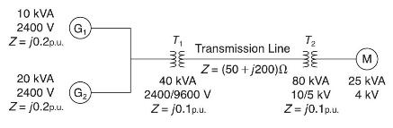
10 KVA 2400 V Z=j0.2p.u. 20 KVA 2400 V Z=j0.2p.u. (G (G) T Transmission Line Z= (50 +1200) 40 KVA 2400/9600 V Z=j0.1p.u. T 80 kVA 10/5 KV Z=j0.1p.u. M 25 KVA 4 kV
Step by Step Solution
3.49 Rating (156 Votes )
There are 3 Steps involved in it

Get step-by-step solutions from verified subject matter experts