

Question: Draw the positive-, negative-, and zero-sequence circuits for the transformers shown in Figure 3.34. Include ideal phase-shifting transformers showing phase shifts. Assume that all windings
Draw the positive-, negative-, and zero-sequence circuits for the transformers shown in Figure 3.34. Include ideal phase-shifting transformers showing phase shifts. Assume that all windings have the same \(\mathrm{kVA}\) rating and that the equivalent leakage reactance of any two windings with the third winding open is 0.10 per unit. Neglect the exciting admittance.
Figure 3.34
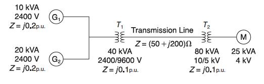
10 KVA 2400 V (G Z=j0.2p.u. 20 KVA 2400 V Z=j0.2p.u. G T Transmission Line Z= (50+j200) 40 KVA 2400/9600 V Z= j0.1p.u. T 80 kVA 10/5 kV Z=j0.1 p.u. M 25 KVA 4 kV
Step by Step Solution
★★★★★
3.43 Rating (150 Votes )
There are 3 Steps involved in it
1 Expert Approved Answer
Step: 1 Unlock

Question Has Been Solved by an Expert!
Get step-by-step solutions from verified subject matter experts
Step: 2 Unlock
Step: 3 Unlock