

Question: For the case of double-circuit, bundle-conductor lines, the same method indicated in Problem 4.27 applies with (r^{prime}) replaced by the bundle's GMR in the calculation
For the case of double-circuit, bundle-conductor lines, the same method indicated in Problem 4.27 applies with \(r^{\prime}\) replaced by the bundle's GMR in the calculation of the overall GMR.
Now consider a double-circuit configuration shown in Figure 4.36 that belongs to a \(500-\mathrm{kV}\), three-phase line with bundle conductors of three subconductors at \(21 \mathrm{in}\). spacing. The GMR of each subconductor is given to be \(0.0485 \mathrm{ft}\).
Determine the inductive reactance of the line in ohms per mile per phase. You may use
\(\mathrm{X}_{\mathrm{L}}=0.2794 \log \frac{\mathrm{GMD}}{\mathrm{GMR}} \Omega / \mathrm{mi} /\) phase
Problem 4.27
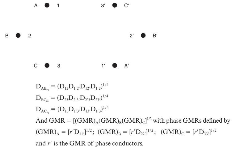
Figure 4.34 shows double-circuit conductors' relative positions in segment 1 of transposition of a completely transposed three-phase overhead transmission line. The inductance is given by
\(\mathrm{L}=2 \times 10^{-7} \ln \frac{\mathrm{GMD}}{\mathrm{GMR}} \mathrm{H} / \mathrm{m} /\) phase Where GMD \(=\left(\mathrm{D}_{\mathrm{AB}_{\mathrm{eq}}} \mathrm{D}_{\mathrm{BC}_{\mathrm{eq}}} \mathrm{D}_{\mathrm{AC}_{\mathrm{eq}}}ight)^{1 / 3}\)
With mean distances defined by equivalent spacings
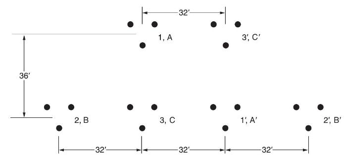
Now consider a 345-kV, three-phase, double-circuit line with phase conductor’s GMR of 0.0588 ft and the horizontal conductor configuration shown in Figure 4.35.
36' 2, B -32'- 1, A 3, C -32- -32'- 3', C' 1; A' -32- 2, B'
Step by Step Solution
3.46 Rating (156 Votes )
There are 3 Steps involved in it
To determine the inductive reactance of the line for the given configuration we will use the formula for inductive reactance XL 02794 log left fracGMD... View full answer

Get step-by-step solutions from verified subject matter experts