

Figure 4.34 shows double-circuit conductors' relative positions in segment 1 of transposition of a completely transposed three-phase
Question:
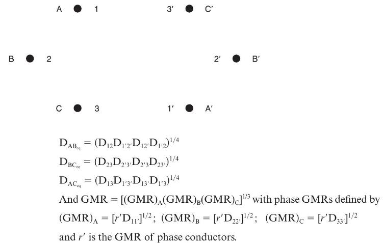
Figure 4.34 shows double-circuit conductors' relative positions in segment 1 of transposition of a completely transposed three-phase overhead transmission line. The inductance is given by
\(\mathrm{L}=2 \times 10^{-7} \ln \frac{\mathrm{GMD}}{\mathrm{GMR}} \mathrm{H} / \mathrm{m} /\) phase Where GMD \(=\left(\mathrm{D}_{\mathrm{AB}_{\mathrm{eq}}} \mathrm{D}_{\mathrm{BC}_{\mathrm{eq}}} \mathrm{D}_{\mathrm{AC}_{\mathrm{eq}}}ight)^{1 / 3}\)
With mean distances defined by equivalent spacings
Now consider a 345-kV, three-phase, double-circuit line with phase conductor’s GMR of 0.0588 ft and the horizontal conductor configuration shown in Figure 4.35.
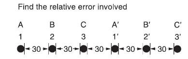
(a) Determine the inductance per meter per phase in Henries (H).
(b) Calculate the inductance of just one circuit and then divide by 2 to obtain the inductance of the double circuit.
Step by Step Answer:


Power System Analysis And Design
ISBN: 9781305632134
6th Edition
Authors: J. Duncan Glover, Thomas Overbye, Mulukutla S. Sarma
