

Question: Reconsider Problem 4.28 with an alternate phase placement given below: Calculate the inductive reactance of the line in (Omega / mathrm{mi} /) phase. Problem 4.28
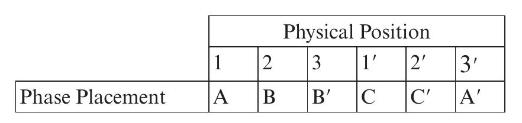
Reconsider Problem 4.28 with an alternate phase placement given below:
Calculate the inductive reactance of the line in \(\Omega / \mathrm{mi} /\) phase.
Problem 4.28
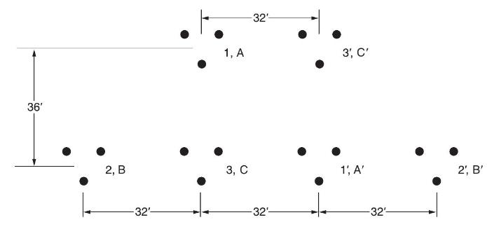
For the case of double-circuit, bundle-conductor lines, the same method indicated in Problem 4.27 applies with \(r^{\prime}\) replaced by the bundle's GMR in the calculation of the overall GMR.
Now consider a double-circuit configuration shown in Figure 4.36 that belongs to a \(500-\mathrm{kV}\), three-phase line with bundle conductors of three subconductors at \(21 \mathrm{in}\). spacing. The GMR of each subconductor is given to be \(0.0485 \mathrm{ft}\).
Determine the inductive reactance of the line in ohms per mile per phase. You may use
\(\mathrm{X}_{\mathrm{L}}=0.2794 \log \frac{\mathrm{GMD}}{\mathrm{GMR}} \Omega / \mathrm{mi} /\) phase
Phase Placement 1 2 A B Physical Position 3 B' 1' C 2' C' 3' A'
Step by Step Solution
3.35 Rating (161 Votes )
There are 3 Steps involved in it
To determine the inductive reactance of the line we can apply the given formula for the inductive re... View full answer

Get step-by-step solutions from verified subject matter experts