

Question: For the circuit given in Problem 13.8, replace the circuit elements by their discrete-time equivalent circuits. Use (Delta t=50 mu mathrm{s}=5 times 10^{-5} mathrm{~s}) and
For the circuit given in Problem 13.8, replace the circuit elements by their discrete-time equivalent circuits. Use \(\Delta t=50 \mu \mathrm{s}=5 \times 10^{-5} \mathrm{~s}\) and \(\mathrm{E}=\) \(100 \mathrm{kV}\). Determine and show all resistance values on the discrete-time circuit. Write nodal equations for the discrete-time circuit, giving equations for all dependent sources. Then solve the nodal equations and determine the sending-and receiving-end voltages at the following times: \(t=50,100\), \(150,200,250\), and \(300 \mu\) s.
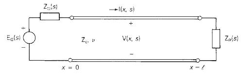
Problem 13.8
The single-phase, two-wire lossless line in Figure 13.3 has a series inductance \(\mathrm{L}=0.999 \times 10^{-6} \mathrm{H} / \mathrm{m}\), a shunt capacitance \(\mathrm{C}=1.112 \times 10^{-11} \mathrm{~F} / \mathrm{m}\), and a \(60-\mathrm{km}\) line length. The source voltage at the sending end is a \(\operatorname{ramp} e_{\mathrm{G}}(t)=\mathrm{E} t u_{-1}(t)=\mathrm{E} u_{-2}(t) \mathrm{kV}\) with a source impedance equal to the characteristic impedance of the line. The receiving-end load consists of a \(150-\Omega\) resistor in parallel with a \(1-\mu \mathrm{F}\) capacitor. The line and load are initially unenergized. Determine
(a) the characteristic impedance in \(\Omega\), the wave velocity in \(\mathrm{m} / \mathrm{s}\), and the transit time in \(\mathrm{ms}\) for this line;
(b) the sending- and receiving-end voltage reflection coefficients in perunit;
(c) the Laplace transform of the sending-end voltage, \(\mathrm{V}_{S}(s)\); and
(d) the sending-end voltage \(v_{\mathrm{S}}(t)\) as a function of time.
Figure 13.3
Eg(s) Z(s) X = 0 Za -1(x, s) V(x, s) X-! ZAIS)
Step by Step Solution
3.56 Rating (153 Votes )
There are 3 Steps involved in it

Get step-by-step solutions from verified subject matter experts