

Question: Re-determine the Example 9_8 fault currents, except with a new line installed between buses 2 and 5. The parameters for this new line should be
Re-determine the Example 9_8 fault currents, except with a new line installed between buses 2 and 5. The parameters for this new line should be identical to those of the existing line between buses 2 and 5 . The new line is not mutually coupled to any other line. Are the fault currents larger or smaller than the Example 9_8 values?
Example 9_8
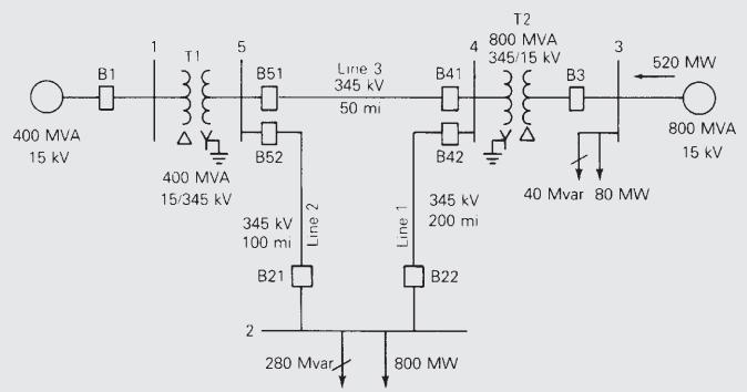
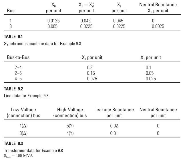
Consider the five-bus power system whose single-line diagram is shown in Figure 6.2. Machine, line, and transformer data are given in Tables 9.1, 9.2, and 9.3. Note that the neutrals of both transformers and generator 1 are solidly grounded, as indicated by a neutral reactance of zero for this equipment. However, a neutral reactance equal to 0.0025 per unit is connected to the generator 2 neutral. The prefault voltage is 1.05 per unit. Using PowerWorld Simulator, determine the fault currents and voltages for a bolted single line-to-ground fault at bus 1 , then bus 2 , and so on to bus 5 .
Figure 6.2
Tables (9.1, 9.2, 9.3)
400 MVA 15 kV B1 1 400 MVA 15/345 kV 5 851 0 B52 345 kV 100 mi B21 2- Line 2 Line 3 345 kV 50 mi 280 Mvar Line 1 B41 B42 345 kV 200 mi B22 4 800 MW T2 800 MVA 345/15 kV B3 3 40 Mvar 80 MW 520 MW 800 MVA 15 kV
Step by Step Solution
3.34 Rating (151 Votes )
There are 3 Steps involved in it

Get step-by-step solutions from verified subject matter experts