

Question: Rework Example 13.6 if the source impedance at the sending end of line (mathrm{A}) is (mathrm{Z}_{mathrm{G}}=mathrm{Z}_{mathrm{A}} / 4=100 Omega), and the receiving end of line
Rework Example 13.6 if the source impedance at the sending end of line \(\mathrm{A}\) is \(\mathrm{Z}_{\mathrm{G}}=\mathrm{Z}_{\mathrm{A}} / 4=100 \Omega\), and the receiving end of line \(\mathrm{B}\) is shortcircuited, \(\mathrm{Z}_{\mathrm{R}}=0\).
Example 13.6
As shown in Figure 13.10, a single-phase lossless overhead line with \(\mathrm{Z}_{\mathrm{A}}=400 \Omega\), \(v_{\mathrm{A}}=3 \times 10^{8} \mathrm{~m} / \mathrm{s}\), and \(l_{\mathrm{A}}=30 \mathrm{~km}\) is connected to a single-phase lossless cable with \(Z_{\mathrm{B}}=100 \Omega, v_{\mathrm{B}}=2 \times 10^{8} \mathrm{~m} / \mathrm{s}\), and \(l_{\mathrm{B}}=20 \mathrm{~km}\). At the sending end of line A, \(e_{g}(t)=\mathrm{E} u_{-1}(t)\) and \(\mathrm{Z}_{\mathrm{G}}=\mathrm{Z}_{\mathrm{A}}\). At the receiving end of line \(\mathrm{B}, \mathrm{Z}_{\mathrm{R}}=2 \mathrm{Z}_{\mathrm{B}}=200 \Omega\). Draw the lattice diagram for \(0 \leq t \leq 0.6 \mathrm{~ms}\) and plot the voltage at the junction versus time. The line and cable are initially unenergized.
Figure 13.10
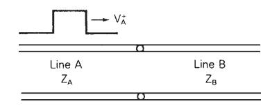
Line A ZA VA Line B ZB
Step by Step Solution
3.50 Rating (160 Votes )
There are 3 Steps involved in it

Get step-by-step solutions from verified subject matter experts