

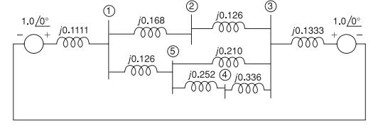
The positive-sequence impedance diagram of a five-bus network with all values in per-unit on a 100-MVA base
Question:
The positive-sequence impedance diagram of a five-bus network with all values in per-unit on a 100-MVA base is shown in Figure 9.25. The generators at buses 1 and 3 are rated 270 and 225 MVA, respectively. Generator reactances include subtransient values plus reactances of the transformers connecting them to the buses. The turns ratios of the transformers are such that the voltage base in each generator circuit is equal to the voltage rating of the generator.
(a) Develop the positive-sequence bus admittance matrix \(\boldsymbol{Y}_{\text {bus 1. }}\)
(b) Using MATLAB or another computer program, invert \(\boldsymbol{Y}_{\text {bus } 1}\) to obtain \(\boldsymbol{Z}_{\text {bus 1 }}\).
(c) Determine the subtransient current for a three-phase fault at bus 4 and the contributions to the fault current from each line. Neglect prefault currents and assume a prefault voltage of 1.0 per unit.
Figure 9.25
Step by Step Answer:


Power System Analysis And Design
ISBN: 9781305632134
6th Edition
Authors: J. Duncan Glover, Thomas Overbye, Mulukutla S. Sarma
