

Question: The full-wave, phase-controlled rectifier of Figure is supplying a highly inductive load such that the load current can be assumed to be purely dc, as
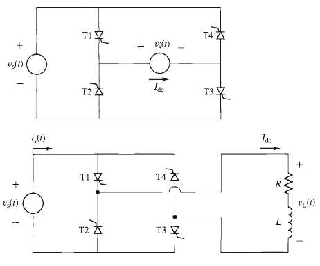
The full-wave, phase-controlled rectifier of Figure is supplying a highly inductive load such that the load current can be assumed to be purely dc, as represented by the current source Idc in the figure. The source voltage is a sinusoid, Vs (t) = V0 sin wt. As shown in Figure, SCRs T1 and T3 are triggered together at delay angle ?d (0 a. For ?d = ?/4:
(i) Sketch the load voltage v`s (t).
(ii) Calculate the average (dc) value Vdc of V's (t).
(iii) Calculate the time-averaged power supplied to the load.
b. Repeat part (a) for ?d = 3?/4.
T4 * + vr) v(1) T2A T3 i,() T1 T4 A "L (r) (1)'a L. T2 A T3 1
Step by Step Solution
3.50 Rating (153 Votes )
There are 3 Steps involved in it
i ii part a iii WIND 08 06 04 02 04 DE DE Sm4 Vac V 77 V... View full answer

Get step-by-step solutions from verified subject matter experts
Document Format (1 attachment)
20-E-E-E-M (259).docx
120 KBs Word File