

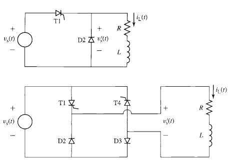
Question: The half-wave, phase-controlled rectifier system of Problem 10.9 and Figure is to be replaced by the full-wave, phase-controlled system of Figure. SCR T1 will be
The half-wave, phase-controlled rectifier system of Problem 10.9 and Figure is to be replaced by the full-wave, phase-controlled system of Figure. SCR T1 will be triggered ON at time td (0 td ?/w), and SCR T4 will be triggered on exactly one half cycle later.
a. Find an expression for the average (dc) value Vdc of the voltage v`s (t) across the series resistor/inductor combination as a function of the delay time td.
b. Using the fact that, in the steady state, there will be zero average voltage across the inductor, find an expression for the dc inductor current Idc, again as a function of the delay time td.
c. Plot Idc as a function of td for (0 td ?/w).
d. Plot the source current is (t) for one cycle of the source voltage for td = 3 msec.
TI D2 A () v(1) L. TI T4 D2 A D3 V
Step by Step Solution
3.33 Rating (162 Votes )
There are 3 Steps involved in it
part a Letting T 2w part b Vac 2 3 ... View full answer

Get step-by-step solutions from verified subject matter experts
Document Format (1 attachment)
20-E-E-E-M (258).docx
120 KBs Word File