

Question: A blending system is shown in Fig. E. Liquid level h and exit composition c3 are to be controlled by adjusting flow rates q1 and
A blending system is shown in Fig. E. Liquid level h and exit composition c3 are to be controlled by adjusting flow rates q1 and q3. Based on the information below, do the following:
(a) Derive the process transfer function matrix, Gp(s).
(b) If a conventional multiloop control system is used, which controller pairing should be used? Justify your answer,
(c) Obtain expressions for the ideal decouplers D21(s) and D12(s) in the configuration of Fig.
Available Information
(i) The tank is 3 ft in diameter and is perfectly mixed.
(ii) Nominal steady-state values are:
(iii) The density of each process stream remains constant at ? = 60 lb/ft3.
(iv) The primary disturbance variable is flow rate q2
. (v) Inlet compositions C1 and C2 arc constant.
(vi) The transmitter characteristics are approximated by the following transfer functions with time constants in minutes:
(vii) Each control valve has a gain of 0.15 ft3/ min mA and a time constant of l0 s.
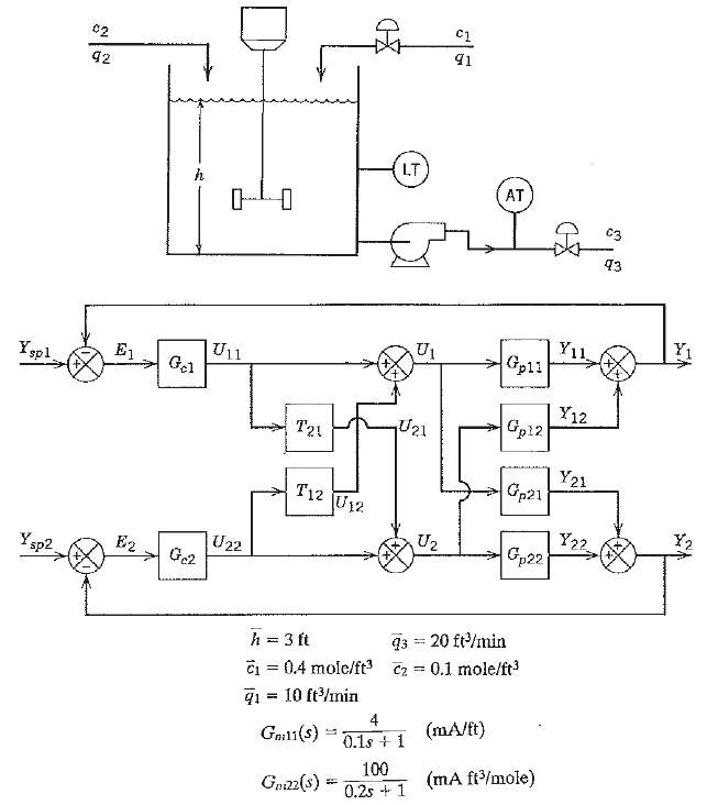
C2 91 92 LT AT C3 43 Y11 Gp11 U1 U11 E1 Yp1 Y12 Cp12 U21 T21 Y21 Gp21 T12 U12 Y2 Y22 Gp22 U2 U22 E2 Y sp2 q3 = 20 ft/min = 0.1 mole/ft h = 3 ft 0.4 mole/ft C2 q1 = 10 ft/min (mA/t) Gml1(s) 0.1s + 1 100 (mA ft/mole) Gnaz(s) 0.2s + 1
Step by Step Solution
3.46 Rating (178 Votes )
There are 3 Steps involved in it
a Material balances for the tank Substituting for d h d t from ... View full answer

Get step-by-step solutions from verified subject matter experts
Document Format (1 attachment)
38-E-C-E-P-C (300).docx
120 KBs Word File