

Question: Consider the liquid level control system shown in the disgram below. Height h of liquid: water (constant density) in the tank (crose-sectional area A=0.25m2 )
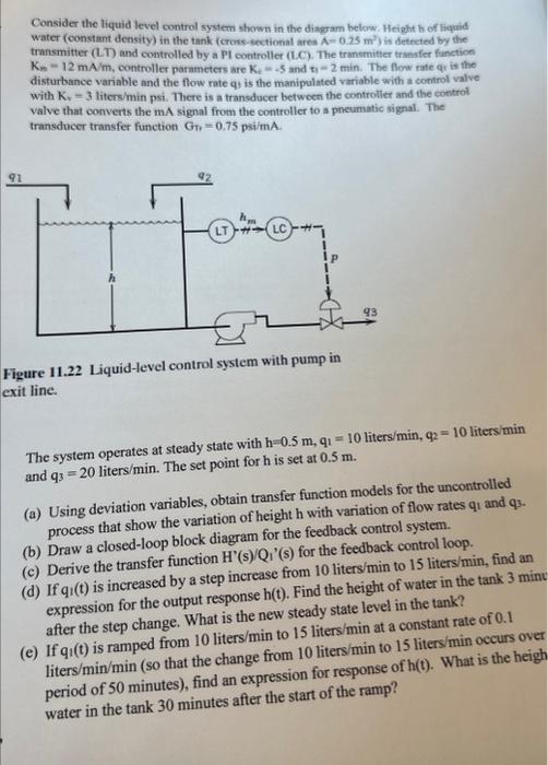
Consider the liquid level control system shown in the disgram below. Height h of liquid: water (constant density) in the tank (crose-sectional area A=0.25m2 ) is defected by the transmitter (LT) and controlled by a PI controller (L.C). The transmitter transfer function Km=12mA/m, controller paratneters are Kii=5 and tri=2 min. The flow rate qt is the disturbance variable and the flow rate qy is the manipulated variable with a control valve with Kv=3 liters/min psi. There is a transducer betwoen the controller and the control valve that converts the mA signal from the controller to a pneumatic signal. The transducer transfer function Grtt=0.75psi/mA. Figure 11.22 Liquid-level control system with pump in exit line. The system operates at steady state with h=0.5m,q1=10 liters /min,q2=10 liters/min and q3=20 liters /min. The set point for h is set at 0.5m. (a) Using deviation variables, obtain transfer function models for the uncontrolled process that show the variation of height h with variation of flow rates q1 and q3. (b) Draw a closed-loop block diagram for the feedback control system. (c) Derive the transfer function H(s)/Qi1(s) for the feedback control loop. (d) If q1(t) is increased by a step increase from 10 liters/min to 15 liters/min, find an expression for the output response h(t). Find the height of water in the tank 3min after the step change. What is the new steady state level in the tank? (e) If q1(t) is ramped from 10 liters/min to 15 liters/min at a constant rate of 0.1 liters /min/min (so that the change from 10 liters /min to 15 liters/min occurs over period of 50 minutes), find an expression for response of h(t). What is the heigh water in the tank 30 minutes after the start of the ramp
Step by Step Solution
There are 3 Steps involved in it

Get step-by-step solutions from verified subject matter experts