

Question: A stirred-tank heat exchanger with a bypass stream is shown in Fig. E. with the available control valves. The possible manipulated variables are: mass flow
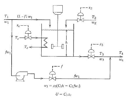
A stirred-tank heat exchanger with a bypass stream is shown in Fig. E. with the available control valves. The possible manipulated variables are: mass flow rate w2, valve stem positions xc and x3, and f, the fraction of mass flow rate w1 that bypasses the tank before being added to the exit stream. Using the information given here, do the following
(a) Derive a dynamic model of the stirred-tank system. Define any additional symbols that you introduce.
(b) Perform the degrees of freedom analysis to determine the degrees of freedom that are available. Allocate the degrees of freedom by specifying manipulated variables and variables that are determined by the environment.
(c) Select controlled variables and briefly justify your choice.
(d) Suppose that only T4 and h are to be controlled by using W2 and f as the manipulated variables. (Valve stem positions, xc and x3, are held constant.) Derive an expression for the relative gain array for this control configuration.
(e) It has been proposed that w2 be replaced by in the control problem of (d). Briefly analyze this proposal. (It is not necessary to perform another RGA analysis.)
Available information
(i) The tank is perfectly mixed, and the temperature changes are relatively small so that constant physical properties can be assumed. Mass flow rates are denoted by w1 to W4 and temperatures by T1 to T4.
(ii) The exit flow rate W3 depends on the pressures upstream and downstream of the control valve, and the valve stem position x3. The following empiric-al relation is available where C1 and C2 are constants:
(iii) The overall heal transfer coefficient for the cooling coil U depends on the velocity of the coolant in the line and hence on the valve stem position xc, according to the relation below where C3 is a constant:
(iv) The pump on the bypass line operates in the flat part? of the pump curve so that the mass how rate, fw1, depends only on the control valve.
(v) The foLlowing process variables remain cons lant T1, w1, T2, and Tc
r-- X2 T2 (1 -/) w1 Te T4 fwr fw 1 w3 = x3(Ch - C2 fwi) U - C3xe
Step by Step Solution
3.58 Rating (166 Votes )
There are 3 Steps involved in it
a Dynamic Model Mass Balance b Degrees of freedom Varia... View full answer

Get step-by-step solutions from verified subject matter experts
Document Format (1 attachment)
38-E-C-E-P-C (304).docx
120 KBs Word File