New Semester
Started
Get
50% OFF
Study Help!
--h --m --s
Claim Now
Question Answers
Textbooks
Find textbooks, questions and answers
Oops, something went wrong!
Change your search query and then try again
S
Books
FREE
Study Help
Expert Questions
Accounting
General Management
Mathematics
Finance
Organizational Behaviour
Law
Physics
Operating System
Management Leadership
Sociology
Programming
Marketing
Database
Computer Network
Economics
Textbooks Solutions
Accounting
Managerial Accounting
Management Leadership
Cost Accounting
Statistics
Business Law
Corporate Finance
Finance
Economics
Auditing
Tutors
Online Tutors
Find a Tutor
Hire a Tutor
Become a Tutor
AI Tutor
AI Study Planner
NEW
Sell Books
Search
Search
Sign In
Register
study help
engineering
civil engineering
Engineering Mechanics Statics 12th Edition R. C. Hibbeler - Solutions
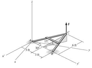
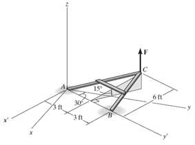
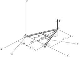
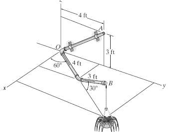
The A-frame is being hoisted into an upright position by the vertical force of F = 80 lb. Determine the moment of this force about the axis y? passing through points A and B when the frame is in the position shown.
The A-frame is being hoisted into an upright position by the vertical force of F = 80 lb. Determine the moment of this force about the x axis when the frame is in the positionshown.
The A-frame is being hoisted into an upright position by the vertical force of F = 80 lb. Determine the moment of this force about the y axis when the frame is in the positionshown.
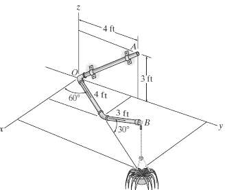
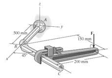
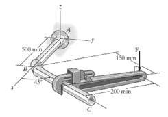
The pipe assembly is secured on the wall by the two brackets. If the flower pot has a weight of 50 lb, determine the magnitude of the moment produced by the weight about the OAaxis.
The pipe assembly is secured on the wall by the two brackets. If the frictional force of both brackets can resist a maximum moment of 150 lb ? f, determine the largest weight of the flower pot that can be supported by the assembly without causing it to rotate about the OA axis.
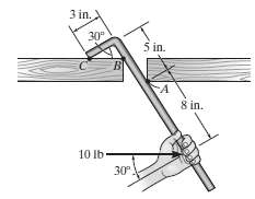
A vertical force of F = 60 N is applied to the handle of the pipe wrench. Determine the moment that this force exerts along the axis AB (x axis) of the pipe assembly. Both the wrench and pipe assembly ABC lie in the x-y plane. Suggestion: Use a scalaranalysis.
Determine the magnitude of the vertical force F acting on the handle of the wrench so that this force produces a component of moment along the AB axis (x axis) of the pipe assembly of (MA)x = {?5i} N ? m. Both the pipe assembly ABC and the wrench lie in the x-y plane. Suggestion: Use a scalar
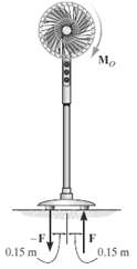
The frictional effects of the air on the blades of the standing fan creates a couple moment of MO = 6 N ? m on the blades. Determine the magnitude of the couple forces at the base of the fan so that the resultant couple moment on the fan is zero.
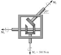
Determine the required magnitude of the couple moments M2 and M3 so that the resultant couple moment iszero.
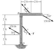
If F = 200 lb, determine the resultant couplemoment.
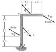
Determine the required magnitude of force F if the resultant couple moment on the frame is 200 lb ? ft, clockwise.
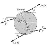
If ? = 30o, determine the magnitude of force F so that the resultant couple moment is 100 N ? m, clockwise.
If F = 200 N, determine the required angle ? so that the resultant couple moment is zero.
Two couples act on the beam. Determine the magnitude of F so that the resultant couple moment is 450 lb ? ft counterclockwise. Where on the beam does the resultant couple moment act?
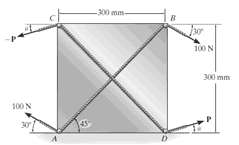
The cord passing over the two small pegs A and B of the board is subjected to a tension of 100 N. Determine the minimum tension P and the orientation ? of the cord passing over pegs C and D, so that the resultant couple moment produced by the two cords is 20 N ? m, clockwise.
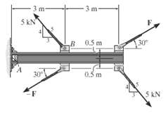
Two couples act on the cantilever beam. If F = 6 kN, determine the resultant couplemoment.
Determine the required magnitude of force F, if the resultant couple moment on the beam is to bezero.
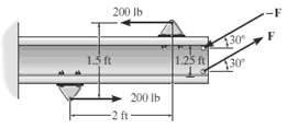
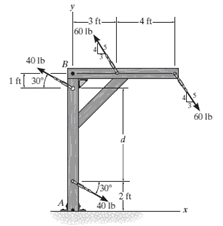
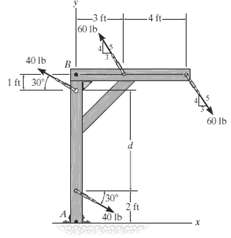
Two couples act on the frame. If d = 4 ft, determine the resultant couple moment. Compute the result by resolving each force into x and y components and (a) Finding the moment of each couple (Eq. 4?13) and (b) Summing the moments of all the force components about point A.
Two couples act on the frame. If d = 4 ft, determine the resultant couple moment. Compute the result by resolving each force into x and y components and (a) Finding the moment of each couple (Eq. 4?13) and (b) Summing the moments of all the force components about point B.
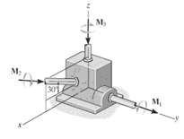
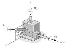
If M1 = 500 N ? m, M2?= 600 N ??m, and, M3 = 450 N ? m, determine the magnitude and coordinate direction angles of the resultant couple moment.
Determine the required magnitude of couple moments M1, M2, and M3 so that the resultant couple moment is MR = {?300i + 450j ? 600k} N ? m.
If F = 80 N, determine the magnitude and coordinate direction angles of the couple moment. The pipe assembly lies in the x?y plane.
If the magnitude of the couple moment acting on the pipe assembly is 50 N ? m, determine the magnitude of the couple forces applied to each wrench. The pipe assembly lies in the x?y plane.
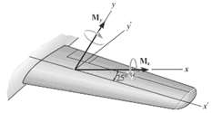
From load calculations it is determined that the wing is subjected to couple moments Mx = 17 kip # ft and My = 25 kip ? ft. Determine the resultant couple moments created about the x? and y? axes. The axes all lie in the same horizontal plane.
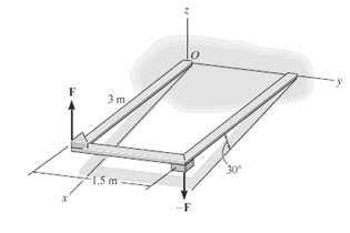
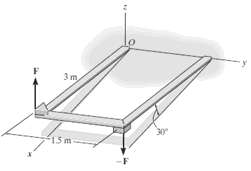
Express the moment of the couple acting on the frame in Cartesian vector form. The forces are applied perpendicular to the frame. What is the magnitude of the couple moment? Take F = 50N.
In order to turn over the frame, a couple moment is applied as shown. If the component of this couple moment along the x axis is Mx = {?20i} N ? m, determine the magnitude F of the couple forces.
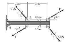
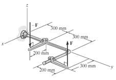
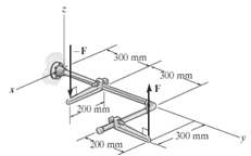
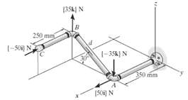
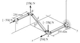
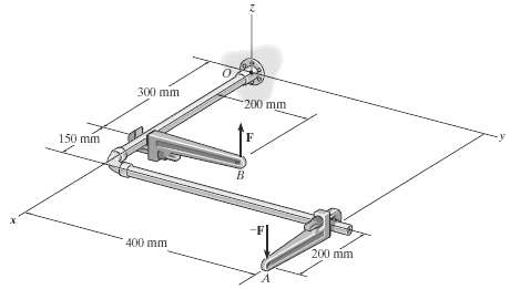
Determine the resultant couple moment of the two couples that act on the pipe assembly. The distance from A to B is d = 400 mm. Express the result as a Cartesianvector.
Determine the distance d between A and B so that the resultant couple moment has a magnitude of MR = 20 N ? m.
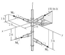
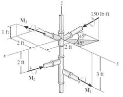
If M1 = 180 lb ? ft, M2 = 90 lb ? ft, and, M3 = 120 lb ? f determine the magnitude and coordinate direction angles of the resultant couple moment.
Determine the magnitudes of couple moments M1, M2, and M3 so that the resultant couple moment iszero.
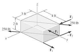
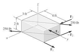
If F1 = 100 lb and F2 = 200 lb, determine the magnitude and coordinate direction angles of the resultant couplemoment.
Determine the magnitude of couple forces F1 and F2 so that the resultant couple moment acting on the block iszero.
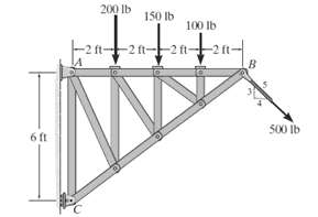
Replace the force system acting on the truss by a resultant force and couple moment at pointC.
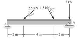
Replace the force system acting on the beam by an equivalent force and couple moment at pointA.
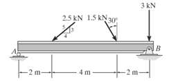
Replace the force system acting on the beam by an equivalent force and couple moment at pointB.
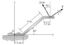
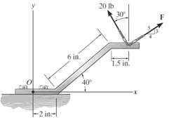
Replace the two forces by an equivalent resultant force and couple moment at point O. Set F = 20lb.
Replace the two forces by an equivalent resultant force and couple moment at point O. Set F = 15lb.
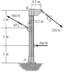
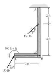
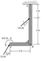
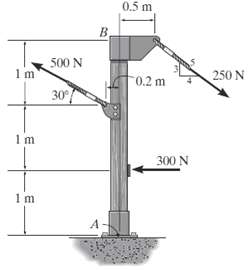
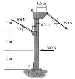
Replace the force system acting on the post by a resultant force and couple moment at pointA.
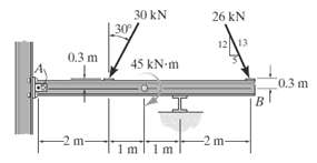
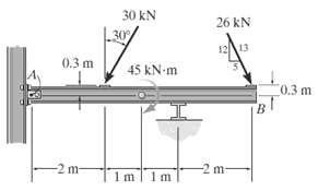
Replace the force and couple moment system acting on the overhang beam by a resultant force and couple moment at pointA.
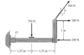
Replace the force system by a resultant force and couple moment at pointO.
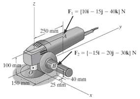
Replace the two forces acting on the grinder by a resultant force and couple moment at point O. Express the results in Cartesian vectorform.
Replace the two forces acting on the post by a resultant force and couple moment at point O. Express the results in Cartesian vectorform.
The three forces act on the pipe assembly. If F1 = 50 N and F2 = 80 N, replace this force system by an equivalent resultant force and couple moment acting at O. Express the results in Cartesian vectorform.
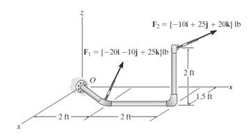
Replace the force system acting on the pipe assembly by a resultant force and couple moment at point O. Express the results in Cartesian vectorform.
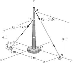
The slab is to be hoisted using the three slings shown. Replace the system of forces acting on slings by an equivalent force and couple moment at point O. The force F1 isvertical.
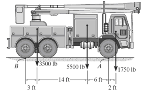
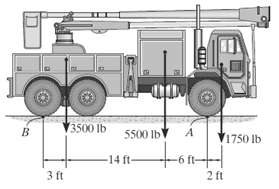
The weights of the various components of the truck are shown. Replace this system of forces by an equivalent resultant force and specify its location measured fromB.
The weights of the various components of the truck are shown. Replace this system of forces by an equivalent resultant force and specify its location measured from pointA.
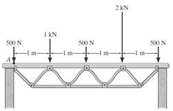
The system of parallel forces acts on the top of the Warren truss. Determine the equivalent resultant force of the system and specify its location measured from pointA.
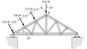
The system of four forces acts on the roof truss. Determine the equivalent resultant force and specify its location along AB, measured from pointA.
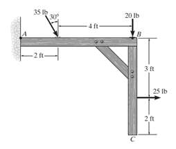
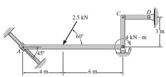
Replace the force and couple system acting on the frame by an equivalent resultant force and specify where the resultant?s line of action intersects member AB, measured from A.
Replace the force and couple system acting on the frame by an equivalent resultant force and specify where the resultant?s line of action intersects member BC, measured from B.
Replace the force and couple moment system acting on the overhang beam by a resultant force, and specify its location along AB measured from pointA.
Replace the force system acting on the frame by an equivalent resultant force and specify where the resultant?s line of action intersects member AB, measured from point A.
Replace the force system acting on the post by a resultant force, and specify where its line of action intersects the post AB measured from pointA.
Replace the force system acting on the post by a resultant force, and specify where its line of action intersects the post AB measured from pointB.
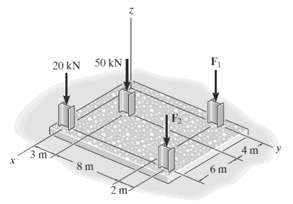
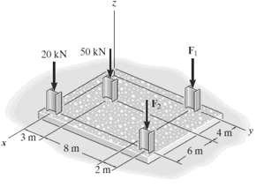
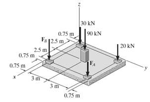
The building slab is subjected to four parallel column loadings. Determine the equivalent resultant force and specify its location (x, y) on the slab. Take F1 = 30 kN, F2 = 40kN.
The building slab is subjected to four parallel column loadings. Determine the equivalent resultant force and specify its location (x, y) on the slab. Take F1 = 20 kN, F2 = 50kN.
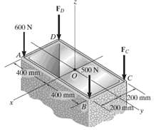
The tube supports the four parallel forces. Determine the magnitudes of forces FC and FD acting at C and D so that the equivalent resultant force of the force system acts through the midpoint O of thetube.
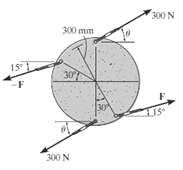
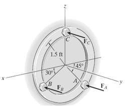
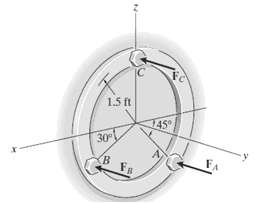
Three parallel bolting forces act on the circular plate. Determine the resultant force, and specify its location (x, z) on the plate. FA = 200 lb, FB = 100 lb, and FC = 400lb.
The three parallel bolting forces act on the circular plate. If the force at A has a magnitude of FA = 200 lb, determine the magnitudes of FB and FC so that the resultant force FR of the system has a line of action that coincides with the yaxis.
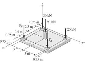
If FA = 40 kN and FB = 35 kN, determine the magnitude of the resultant force and specify the location of its point of application (x, y) on the slab.
If the resultant force is required to act at the center of the slab, determine the magnitude of the column loadings FA and FB and the magnitude of the resultantforce.
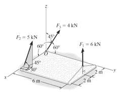
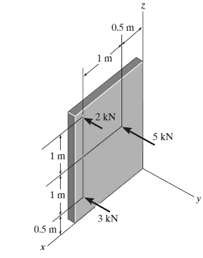
Replace the parallel force system acting on the plate by a resultant force and specify its location on the x?z plane.
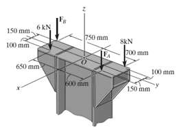
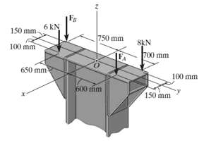
If FA = 7 kN and FB = 5 kN, represent the force system acting on the corbels by a resultant force, and specify its location on the x?y plane.
Determine the magnitudes of FA and FB so that the resultant force passes through point O of thecolumn.
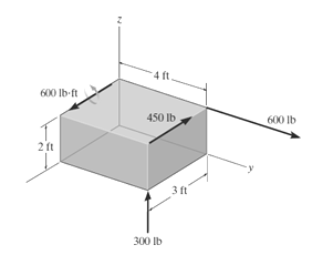
Replace the force and couple moment system acting on the rectangular block by a wrench. Specify the magnitude of the force and couple moment of the wrench and where its line of action intersects the x–y plane.
Replace the three forces acting on the plate by a wrench. Specify the magnitude of the force and couple moment for the wrench and the point P(y, z) where its line of action intersects theplate.
Replace the distributed loading with an equivalent resultant force, and specify its location on the beam measured from pointA.
Replace the distributed loading with an equivalent resultant force, and specify its location on the beam measured from pointA.
Replace the distributed loading by an equivalent resultant force and specify its location, measured from pointA.
Replace the distributed loading with an equivalent resultant force, and specify its location on the beam measured from pointA.
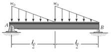
Determine the intensities w1 and w2 of the distributed loading acting on the bottom of the slab so that this loading has an equivalent resultant force that is equal but opposite to the resultant of the distributed loading acting on the top of theplate.
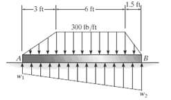
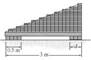
The bricks on top of the beam and the supports at the bottom create the distributed loading shown in the second figure. Determine the required intensity w and dimension d of the right support so that the resultant force and couple moment about point A of the system are bothzero.
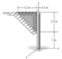
The wind pressure acting on a triangular sign is uniform. Replace this loading by an equivalent resultant force and couple moment at pointO.
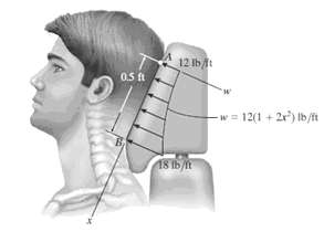
Currently eighty-five percent of all neck injuries are caused by rear-end car collisions. To alleviate this problem, an automobile seat restraint has been developed that provides additional pressure contact with the cranium. During dynamic tests the distribution of load on the cranium has been
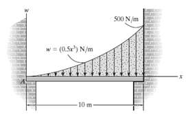
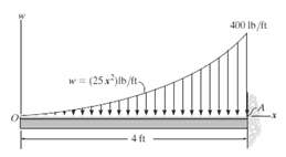
Wind has blown sand over a platform such that the intensity of the load can be approximated by the function w = (0.5x3) N/m. Simplify this distributed loading to an equivalent resultant force and specify its magnitude and location measured fromA.
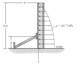
Wet concrete exerts a pressure distribution along the wall of the form. Determine the resultant force of this distribution and specify the height h where the bracing strut should be placed so that it lies through the line of action of the resultant force. The wall has a width of 5m.
Replace the distributed loading with an equivalent resultant force, and specify its location on the beam measured from pointA.
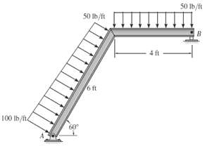
Replace the loading by an equivalent resultant force and couple moment at pointA.
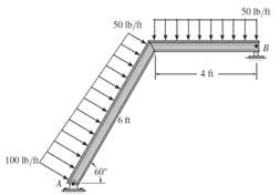
Replace the loading by an equivalent resultant force and couple moment acting at pointB.
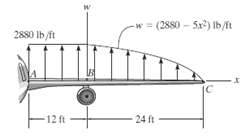
The lifting force along the wing of a jet aircraft consists of a uniform distribution along AB, and a semiparabolic distribution along BC with origin at B. Replace this loading by a single resultant force and specify its location measured from pointA.
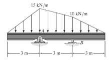
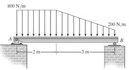
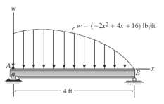
The distributed load acts on the beam as shown. Determine the magnitude of the equivalent resultant force and specify where it acts, measured from pointA.
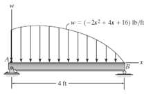
The distributed load acts on the beam as shown. Determine the maximum intensity wmax. What is the magnitude of the equivalent resultant force? Specify where it acts, measured from pointB.
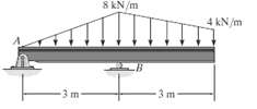
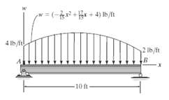
The distributed load acts on the beam as shown. Determine the magnitude of the equivalent resultant force and specify its location, measured from pointA.
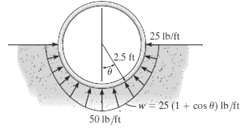
If the distribution of the ground reaction on the pipe per foot of length can be approximated as shown, determine the magnitude of the resultant force due to thisloading.
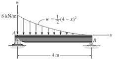
The beam is subjected to the parabolic loading. Determine an equivalent force and couple system at pointA.
Express the moment of the couple acting on the pipe assembly in Cartesian vector form. Solve the problem (a) Using Eq. 4?13 and (b) Summing the moment of each force about point O. Take F = {25k} N.
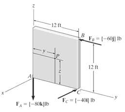
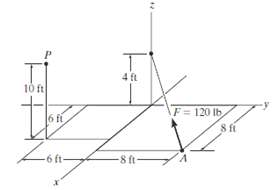
Replace the force at A by an equivalent resultant force and couple moment at point P. Express the results in Cartesian vectorform.
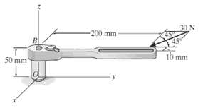
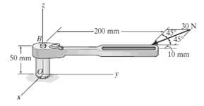
The horizontal 30-N force acts on the handle of the wrench. Determine the moment of this force about point O. Specify the coordinate direction angles ?, ?, ? of the moment axis.
The horizontal 30-N force acts on the handle of the wrench. What is the magnitude of the moment of this force about the zaxis?
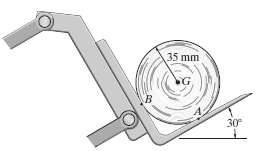
Draw the free-body diagram of the 50-kg paper roll which has a center of mass at G and rests on the smooth blade of the paper hauler. Explain the significance of each force acting on the diagram. (SeeFigure)
Draw the free-body diagram of member AB, which is supported by a roller at A and a pin at B. Explain the significance of each force on the diagram. (SeeFig)
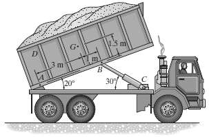
Draw the free-body diagram of the dumpster D of the truck, which has a weight of 5000 lb and a center of gravity at G. It is supported by a pin at A and a pin-connected hydraulic cylinder BC (short link). Explain the significance of each force on the diagram. (SeeFig)
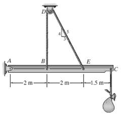
Draw the free-body diagram of the beam which supports the 80-kg load and is supported by the pin at A and a cable which wraps around the pulley at D. Explain the significance of each force on the diagram. (SeeFig)
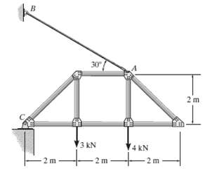
Draw the free-body diagram of the truss that is supported by the cable AB and pin C. Explain the significance of each force acting on the diagram. (SeeFig)
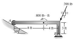
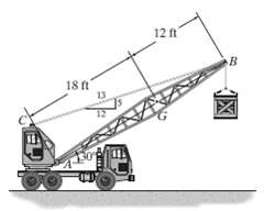
Draw the free-body diagram of the crane boom AB which has a weight of 650 lb and center of gravity at G. The boom is supported by a pin at A and cable BC. The load of 1250 lb is suspended from a cable attached at B. Explain the significance of each force acting on the diagram. (SeeFig)
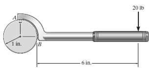
Draw the free-body diagram of the ?spanner wrench? subjected to the 20-lb force. The support at A can be considered a pin, and the surface of contact at B is smooth. Explain the significance of each force on the diagram. (See Fig)
Draw the free-body diagram of member ABC which is supported by a smooth collar at A, roller at B, and short link CD. Explain the significance of each force acting on the diagram. (SeeFig)
Draw the free-body diagram of the bar, which has a negligible thickness and smooth points of contact at A, B, and C. Explain the significance of each force on the diagram. (See Fig)
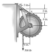
Draw the free-body diagram of the winch, which consists of a drum of radius 4 in. It is pin-connected at its center C, and at its outer rim is a ratchet gear having a mean radius of 6 in. The pawl AB serves as a two-force member (short link) and prevents the drum from rotating. Explain the
Showing 1700 - 1800
of 2574
First
11
12
13
14
15
16
17
18
19
20
21
22
23
24
25
Last
Step by Step Answers