

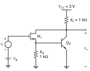
A BiCMOS Darlington is shown in Fig. 3.76. The bias voltage V B is adjusted for a
Question:
Fig. 3.76:
Fantastic news! We've Found the answer you've been seeking!
Step by Step Answer:
V o 2V dc I C I D 1 mA I D 011 k 07 mA I C 03 mA V BE V T n 03 m...View the full answer

Answered By
Leah Muchiri
I am graduate in Bachelor of Actuarial Science and a certified accountant. I am also a prolific writer with six years experience in academic writing. My working principle are being timely and delivering 100% plagiarized free work. I usually present a precised solution to every work am assigned to do. Most of my student earn A++ GRADE using my precised and correct solutions.
52+ Reviews
125+ Question Solved
Related Book For 

Analysis and Design of Analog Integrated Circuits
ISBN: 978-0470245996
5th edition
Authors: Paul R. Gray, Paul J. Hurst Stephen H. Lewis, Robert G. Meyer
Question Posted:
