

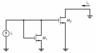
Question: Replace the MOS transistors in the amplifier in Fig. 7.45 with bipolar npn transistors. The emitter area of Q 2 is four times that of
Replace the MOS transistors in the amplifier in Fig. 7.45 with bipolar npn transistors. The emitter area of Q2is four times that of Q1and corresponding bias currents are IC1= 1 mA and IC2= 4 mA. Repeat the calculations in Problem 7.33 using the following data. Data at the operating point: Q1: β = 200, Ï„F = 0.2 ns, Cμ= 0.2 pF, Cje= 1 pF, Ccs= 1 pF, rb= 0, and ro= ˆž.Q2: β = 200, Ï„F= 0.2 ns, Cμ= 0.8 pF, Cje= 4 pF, Ccs= 4 pF, rb= 0, and ro= ˆž.
Fig. 7.45:
M2 M1
Step by Step Solution
3.45 Rating (161 Votes )
There are 3 Steps involved in it
V i i i 2537 For Q 1 C b F g m1 C 1 87 pF For ... View full answer

Get step-by-step solutions from verified subject matter experts
Document Format (2 attachments)
1528_605d88e1b9ede_686943.pdf
180 KBs PDF File
1528_605d88e1b9ede_686943.docx
120 KBs Word File