

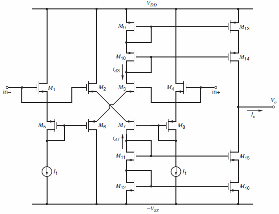
The CMOS circuit of Fig. 9.56 is to be used as a high-slew-rate op amp. A load
Question:
Figure 9.56:
Fantastic news! We've Found the answer you've been seeking!
Step by Step Answer:
dc bias I D 20A I 1 in all devices gain A V G m R o 219 AV 219 AV V t3 V t6 V GS3 V G...View the full answer

Answered By
Mamba Dedan
I am a computer scientist specializing in database management, OS, networking, and software development. I have a knack for database work, Operating systems, networking, and programming, I can give you the best solution on this without any hesitation. I have a knack in software development with key skills in UML diagrams, storyboarding, code development, software testing and implementation on several platforms.
60+ Reviews
144+ Question Solved
Related Book For 

Analysis and Design of Analog Integrated Circuits
ISBN: 978-0470245996
5th edition
Authors: Paul R. Gray, Paul J. Hurst Stephen H. Lewis, Robert G. Meyer
Question Posted:
