

Question: Repeat Problem 9.25 except, for the op amp, use the aspect ratios, supply voltages, and bias current given in Fig. 6.58 instead of the values
Repeat Problem 9.25 except, for the op amp, use the aspect ratios, supply voltages, and bias current given in Fig. 6.58 instead of the values in Fig. 9.60. Also, for the bias circuit, use the aspect ratios, supply voltages, and bias current given in Problem 9.24. Ignore junction capacitance for all transistors. Also, assume that Xd= 0.1 µm for all transistors operating in the active region, and use Table 2.4 for other parameters.
Data from Prob. 9.25:
Assuming that the zero has been moved to infinity, determine the maximum load capacitance that can be attached directly to the output of the circuit of Fig. 9.60 and still maintain a phase margin of 45°. Neglect all higher order poles except any due to the load capacitance. Use the value of W/L obtained in Problem 9.23 for M9 with the bias circuit of Fig. 9.61.
Fig. 9.60:
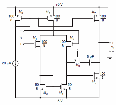
Fig. 9.61:
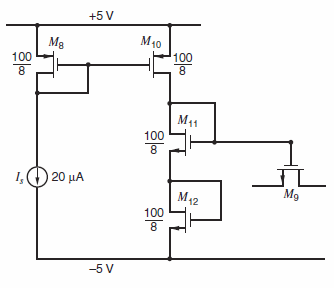
Figure 6.58:
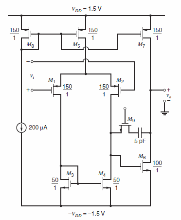
Table 2.4:
+5 V Mg M5 100 M, 100 100 Vi . M2 100 100 Vo 5 pF 20 (1) M9 100 M6 50 50 -5 V +5 V Mg 100 M40 100 8. M41 100 1O 20 A M42 100 8. Mg -5 V
Step by Step Solution
3.27 Rating (162 Votes )
There are 3 Steps involved in it
To obtain 45 phase margin set the 2 nd pole to funity 328 ... View full answer

Get step-by-step solutions from verified subject matter experts
Document Format (2 attachments)
1528_605d88e1c6028_687077.pdf
180 KBs PDF File
1528_605d88e1c6028_687077.docx
120 KBs Word File