

Figure P17.12 shows the surge control loop of a compressor. The condensate in the feed and recycle
Question:
Figure P17.12 shows the surge control loop of a compressor. The condensate in the feed and recycle stream is drained from V-1105. Then the feed gas is compressed to 25 bar in a compressor and sent to a knockout drum, V-1106. The condensate-free gas from the top of V-1106 is split into two portions. One portion goes out as product while the other portion is recycled to the compressor suction to prevent surge.
Figure P17.12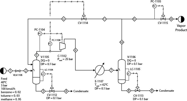
1. Develop a steady-state model of this system. The suggested thermopackage is PR EOS. The isentropic efficiency of C-1102 is 80%. At steady state, there is no recycle flow; that is, flow of Stream 11 is zero.
2. Develop a dynamic model of this system. Heat loss to the environment for all equipment can be neglected. Size V-1105 and V-1106 following the heuristics. In Figure P17.12, FC-1108 is the anti-surge controller. Compressor surge control algorithms, in general, can be very involved. For simplicity, it can be assumed that if the molar flowrate of Stream 5 can be maintained within 90% of its steady-state value, a surge can be prevented. Therefore, in case of a disturbance, FC-1108 should be able to maintain the flow of Stream 5 within 90% of its set point. When sizing CV-1114, it should be ensured that it can maintain the required flow of Stream 5 even if the flowrate of Stream 1 becomes zero. Determine the “best” set of tuning parameters that provides satisfactory performance when VLV-1105 is completely closed. To reiterate the control performance requirement, the flow of Stream 5 should be maintained within 90% of its steady-state value with no or negligible oscillation. This constraint should be satisfied along with satisfactory performance of PC-1104, PC-1105, and LC-1105.
3. In Part (b), if performance of any or some of these controllers is not satisfactory, what would you suggest for improvement? You may suggest hardware modification(s).
4. For this system, it is known that the pressure of Stream 1 may increase up to 3.2 bar under certain circumstances. To check the performance of the control system for this disturbance, again consider that the process is at steady state with the flow of Stream 1 being at 100 kmol/h. Now increase the pressure of Stream 1 from 3 bar to 3.2 bar. Do you get satisfactory performance with the previous tuning parameters, especially for LC-1105 and PC-1105? If not, why?
5. What would be your suggested overall improvement in the process design, including control system improvement and hardware modification, so that the control system performance is satisfactory for the disturbance considered in Part (b) and in this problem? Implement your suggestions and compare the performance of the control system with the performance that you obtained before.
Step by Step Answer:


Analysis Synthesis And Design Of Chemical Processes
ISBN: 9780134177403
5th Edition
Authors: Richard Turton, Joseph Shaeiwitz, Debangsu Bhattacharyya, Wallace Whiting
