New Semester
Started
Get
50% OFF
Study Help!
--h --m --s
Claim Now
Question Answers
Textbooks
Find textbooks, questions and answers
Oops, something went wrong!
Change your search query and then try again
S
Books
FREE
Study Help
Expert Questions
Accounting
General Management
Mathematics
Finance
Organizational Behaviour
Law
Physics
Operating System
Management Leadership
Sociology
Programming
Marketing
Database
Computer Network
Economics
Textbooks Solutions
Accounting
Managerial Accounting
Management Leadership
Cost Accounting
Statistics
Business Law
Corporate Finance
Finance
Economics
Auditing
Tutors
Online Tutors
Find a Tutor
Hire a Tutor
Become a Tutor
AI Tutor
AI Study Planner
NEW
Sell Books
Search
Search
Sign In
Register
study help
business
systems analysis and design
Heating Ventilating And Air Conditioning Analysis And Design 6th Edition Faye C. McQuiston, Jerald D. Parker, Jeffrey D. Spitler - Solutions
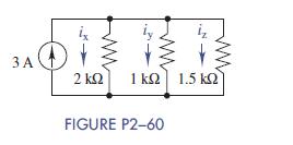
2–60 Use current division in Figure P2−60 to find ix, iy, and iz.Then show that the sum of these currents equals the source current. 3 A 2 kt2 1k2] 1.5 k2] FIGURE P2-60
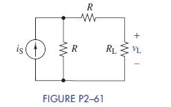
2–61 Use current division in Figure P2−61 to find an expression for vL in terms of R, RL, and iS. is R w w R RL w FIGURE P2-61 + VL
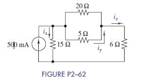
2–62 Find ix, iy, and iz in Figure P2−62. 2002 w 502 ww 500 mA 15 6 FIGURE P2-62
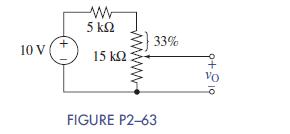
2–63 Find vO in the circuit of Figure P2−63. 10 V + ww 5 15 FIGURE P2-63 33% Vo
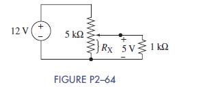
2–64 You wish to drive a 1-kΩ load from your car battery as shown in Figure P2−64. The load needs 5 V across it to operate correctly. Where should the wiper on the potentiometer be set (Rx) to obtain the desired output voltage? 12 V + 5 Rx 5V 1 kQ FIGURE P2-64
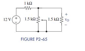
2–65 Find the range of values of vO in Figure P2−65. www 12 V(+ 1.5 1.5 Vo FIGURE P2-65 +
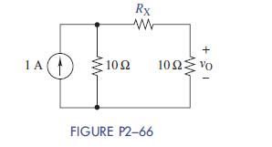
2–66 Use current division in the circuit of Figure P2−66 to find RX so that the voltage out is 3 V. Repeat for 5 V. 1 A 100 Rx www w + 10 102 w FIGURE P2-66
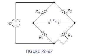
2–67 Figure P2−67 shows a voltage bridge circuit, that is, two voltage dividers in parallel with a source vS. One resistor RX is variable. The goal is often to “balance”the bridge by making vx = 0 V. Derive an expression for RX in terms of the other resistors for when the bridge is
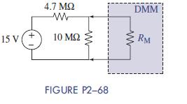
2–68 Ideally, a voltmeter has infinite internal resistance and can be placed across any device to read the voltage without affecting the result. A particular digital multimeter (DMM), a common laboratory tool, is connected across the circuit shown in Figure P2−68. The expected voltage was 10.2
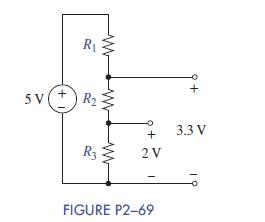
2–69 Select values for R1, R2, and R3 in Figure P2−69 so that the voltage divider produces the two output voltages shown. R 5V +R I ww + 3.3 V R3 2 V FIGURE P2-69
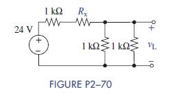
2–70 Select a value of Rx in Figure P2−70 so that vL = 4V 24 V 1 ww + Rx ww VL FIGURE P2-70
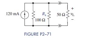
2–71 Select a value of Rx in Figure P2−71 so that vL = 2 V. Repeat for 4 V and 6 V. Caution: Rx must be positive 120 mA 100 +21 Rx 502VL FIGURE P2-71
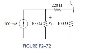
2–72 Use circuit reduction to find vx and ix in Figure P2−72. 100 mA 220 w 100 . 100 www FIGURE P2-72
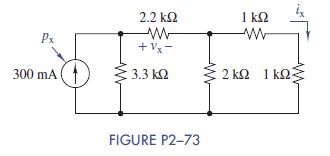
2–73 Use circuit reduction to find vx, ix, and px in Figure P2−73.Repeat using Multisim Px 2.2 +x- 300 mA ( - 3.3 1 w 2 FIGURE P2-73
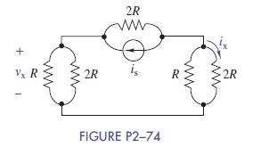
2–74 Use circuit reduction to find vx and ix in Figure P2−74. + Vx R 2R 2R R FIGURE P2-74 2R
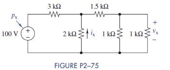
2–75 Use circuit reduction to find vx, ix, and px in Figure P2−75. 3 Px 1.5 w + 100 V 2 FIGURE P2-75 +
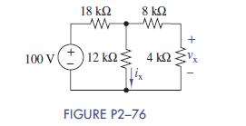
2–76 Use circuit reduction to find vx and ix in Figure P2−76. 18 www 8 w + V. 100 V12 k 4kQ: Lix FIGURE P2-76
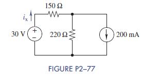
2–77 Use source transformation to find ix in Figure P2−77. ix 150 w 30 V 220 200 mA FIGURE P2-77
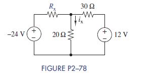
2–78 Select a value for Rx so that ix = 0A in Figure P2−78. RX 30 www -24 V(+ 20.02 www +12 V FIGURE P2-78
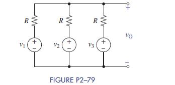
2–79 Use source transformations in Figure P2−79 to relate vO to v1, v2, and v3. R V 1+ www R V2 www + I R vo V3 FIGURE P2-79 +1
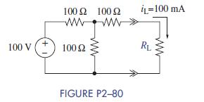
2–80 The current through RL in Figure P2−80 is 100 mA. Use source transformations to find RL. Validate your answer using Multisim. 100 100 www 100 V +100 2 IL-100 mA RL FIGURE P2-80
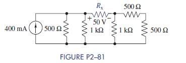
2–81 Select Rx so that 50 V is across it in Figure P2−81. Rx ww 50 V 500 www 400 mA 1500 1 1 500 FIGURE P2-81
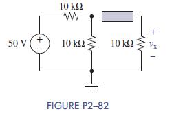
2–82 The box in the circuit in Figure P2−82 is a resistor whose value can be anywhere between 8 and 80 kΩ. Use circuit reduction to find the range of values of vx. 50 V +1 10 ww 10 10 FIGURE P2-82
2–83 Use Multisim to find all the currents and voltages in the circuit of Figure P2−76.
2–84 Use Multisim to find all the currents and voltages in the circuit of Figure P2−77.
2–85 Use Multisim to find ix, vx, and px in the circuit of Figure P2−73.
2–86 Use Multisim to show the power balance in the circuit of Figure P2−72, that is, that the sum of the power in the circuit equals zero.
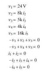
2–87 A circuit is found to have the following element and connection equationsUseMATLABto solve for all of the unknown voltages and currents associated with this circuit. Sketch one possible schematic that matches the given equations. V = 24 V V = 8k i V3 = 5k iz V4= 4k i4 vs = 16k is -V1+V2+V3 0
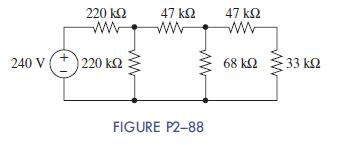
2–88 Consider the circuit of Figure P2−88. Use MATLAB to find all of the voltages and currents in the circuit and find the power provided by the source. 220 www 47 www 47 www 240 V 220 68 33 FIGURE P2-88
2–89 Consider the circuit of Figure P2−88 again. Use Multisim to find all of the voltages, currents, and power used or provided. Verify that the sum of all power in the circuit is zero.
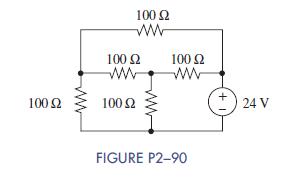
2–90 The circuit of Figure P2−90 is called a “bridge-T” circuit.Use Multisim to find all of the voltages and currents in the circuit. 100 www 100 www 100 100 www 100 ww FIGURE P2-90 +1 24 V
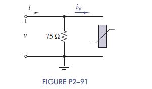
2–91 Nonlinear Device Characteristics The circuit in Figure P2−91 is a parallel combination of a 75-Ω linear resistor and a varistor whose i – v characteristic is iV = 2:6 × 10⁻⁵v3. For a small voltage, the varistor current is quite small compared to the resistor current.For large
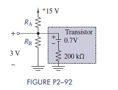
2–92 Transistor Biasing The circuit shown in Figure P2−92 is a typical biasing arrangement for a BJT-type transistor. The actual transistor for this problem can be modeled as 0:7-V battery in series with a 200-kΩ resistor. Biasing allows signals that have both positive and negative variations
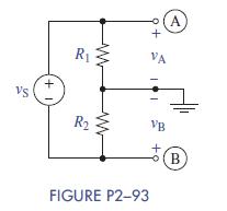
2–93 Center Tapped Voltage Divider Figure P2−93 shows a voltage divider with the center tap connected to ground. Derive equations relating vA and vB to vS, R1, and R2. VS +1 R VA A R VB B FIGURE P2-93
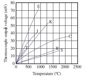
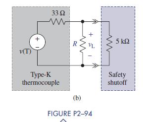
2–94 Thermocouple Alarm Sensor A type-K thermocouple produces a voltage that is proportional to temperature. The characteristic of a type-K thermocouple is shown in Figure P2−94(a). In an application, this transducer is used to detect when the temperature reaches 1250C and then to cause a
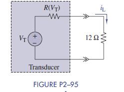
2–95 Active Transducer Figure P2−95 shows an active transducer whose resistance RðVTÞ varies with the transducer voltage VT as RðVTÞ =0:5 VT 2 + 1. The transducer supplies a current to a 12-Ω load.At what voltage will the load current equal 100 mA? VT R(VT) www Transducer FIGURE P2-95
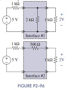
2–96 Interface Circuit Choice You have a practical voltage source that can be modeled as a 5-V ideal source in series with a 1-kΩ source resistor. You need to use your source to drive a 1-kΩ load that requires exactly 2 V across it. Two solutions are provided to you as shown in Figure P2−96.
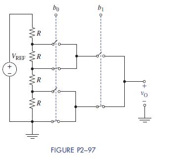
2–97 Programmable Voltage Divider Figure P2−97 shows a programmable voltage divider in which digital inputs b0 and b1 control complementary analog switches connecting a multitap voltage divider to the analog output vO.The switch positions in the figure apply when digital inputs are low. When
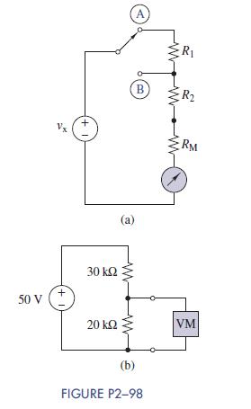
2–98 Analog Voltmeter Design Figure P2−98(a) shows a voltmeter circuit consisting of a D’Arsonval meter, two series resistors, and a twoposition selector switch. A current of IFS = 400 μA produces full-scale deflection of the D’Arsonval meter, whose internal resistance is RM = 25Ω.(a)
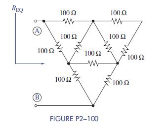
2–100 Finding an Equivalent Resistance using Multisim Use Multisim to find the equivalent resistance at terminals A and B of the resistor mesh shown in Figure P2−100. (Hint:Use a 1-V dc source and measure the current provided by the source.) REQ 100 B 100 w 100 100 w 100 100 100 ww 100
=+14-1. Five thousand cfm (2.36 m3/s) of standard air are heated to 120 F (50 C) in a cross-flow heat exchanger with fluids unmixed. The heating medium is water at 200 F (95 ℃), which is cooled to 180 F (82 C). Determine (a) the LMTD and correction factor F. (b) the fluid capacity rates
=+C. and C), (c) the flow rate of the water in gpm (m3/s). (d) the overall conductance UA. (e) the NTU based on Cmin. and (1) the effectiveness €.
=+14-2.A heat exchanger is to be designed to heat 4000 cfm (1.9 m3/s) of air from 50 F (10 C) to 110 F(43 C) using hot water at 180 F (82 C) in a cross-flow arrangement with fluids unmixed. The flow rate of the hot water is 25 gpm (1.6 L/s). Assume the overall heat-transfer coefficient based on the
=+(a) the LMTD method and (b) the NTU method.
=+14-3.An air-cooled condenser operates in cross flow with a constant refrigerant temperature of 125 F(52 C). The air enters at 95 F (35 C) at a flow rate of 3200 cfm (1.5 m3/s). The air-side surface area is 300 ft2 (28 m2), and the overall heat-transfer coefficient is 10 Btu/(hr-ftª-F) [57
=+14-4.A tube has circular fins as shown in Fig. 14-26; R is 1.0 in, whereas r is 0.5 in. The fin thick-ness y is 0.008 in ., and the fin pitch is 10 fins/in. The average heat-transfer coefficient for the fin and tube is 10 Btu/(hr-ft2-F), whereas the thermal conductivity k of the fin and tube
=+14-5.Find the surface effectiveness for the finned tube in Problem 14-4 assuming the ratio of fin area to total area is 0.9.
=+14-6.The finned tube of Problem 14-4 has a refrigerant flowing on the inside with an average heat-transfer coefficient of 200 Btu/(hr-ft2-F). The tube wall has a thickness of 0.015 in. Compute the overall heat-transfer coefficient based on the air-side surface area. Assume that the ratio of
=+14-7.Water flows through the finned tube in Problem 14-4. Find the overall heat-transfer coefficient assuming a water heat-transfer coefficient of 1100 Btu/(hr-fr"-F).
=+14-8.A plate-fin heat exchanger has fins that are 6 mm high and 0. 16 m thick, with a fin pitch of 0.47 fins/mm. The average heat-transfer coefficient is 57 W/(m.C), and the thermal conduc-tivity of the fin material is 173 W/(m-C). Find the fin efficiency.
=+149.Assume that the ratio of fin area to total area in Problem 14-8 is 0.85. Find the surface effectiveness.
=+14-10 Refrigerant 134a flows on the opposite side of the surface in Problem 14-8. Determine the over-all heat-transfer coefficient if the refrigerant heat-transfer coefficient is 1.4kW/(m2-C). Neglect the thermal resistance of the plate.
=+14-11.Find the fin efficiency for a plate-fin-tube surface like that shown in Fig. 14-7. using the data shown in Table 14-2.
=+14-12. Assume that water is flowing in the finned tubes of Problem 14-11 with a heat-transfer coeffi-cient of 600 Btu/(hr-ft2-F) [3.4 kW/(m2-C)], and compute the overall heat-transfer coefficient.Assume that the ratio of fin area to total air-side area is 0.9 and the ratio of air-side arca to
=+14-13 Compute the contact resistance for the surface of Problem 14-11. Assume a fin pitch of 12 fins per inch.
=+14-14. Determine the average heat-transfer coefficient for water flowing in a ¿ in. type L copper tube.The water flows at a rate of : gpm (0.16 L/s) and undergoes a temperature change from 180(82 C) to 150 F (66 C). The tube is over 4 ft (1.5 m) long.
=+14-15.Repeat Problem 14-14 for a 30 percent ethylene glycol solution.
=+14-16.Rework Problem 14-14 for a 60 percent ethylene glycol solution.
=+14-17.Estimate the heat-transfer coefficient for water flowing with an average velocity of 4 fu/sec(1.2 m/s) in a long rectangular 3 × 1 in. (75 x 25 mm) channel. The bulk temperature of the water is 45 F (7 C). Assume (a) cooling and (b) heating.
=+14-18. Repeat Problem 14-17 for 30 percent ethylene glycol instead of water.
=+14-19. Coolant flows through a long 12 mm I.D. tube with an average velocity of 1.5 m/s. The coolant undergoes a temperature change from 40 to 50 C. Compute the average heat-transfer coeffi-cient for (a) water and (b) 30 percent ethylene glycol solution.
=+14-20.Water flows through a 0.34 in. I.D. tube with an average velocity of _ fu/sec. The mean bulk temperature of the water is 45 F. and the length of the tube is 10 ft. Estimate the average heat-transfer coefficient for (a) water and (b) ethylene glycol (30 percent solution).
=+14-21.Estimate the average heat-transfer coefficient for water flowing in 10 mm L.D. tubes at a veloc-ity of 0.10 m/s. The length of the tubes is 3 m, and the mean bulk temperature of the water is 40 C.
=+14-22.Estimate the average heat-transfer coefficient for condensing water vapor in §in. O.D. tubes that have walls 0.018 in. thick. The vapor is saturated at 5 psia and flows at the rate of 1 Ibm/hr at the tube inlet. The quality of the vapor is 10 percent when it exits from the tube.
=+14-23.Water vapor condenses in 15 mm I.D. tubes. The flow rate is 0.126 × 10⁻³ kg/s per tube at an absolute pressure of 35 kPa. The vapor leaving the tubes has a quality of 12 percent. Estimate the average heat-transfer coefficient.
=+14-24.Refrigerant 22 enters the § in. O.D. tubes of an evaporator at the rate of 80 Ibm/hr per tube.The refrigerant enters at 70 psia with a quality of 20 percent and leaves with 10 F of superheat.
=+The effective tube length is 5 ft. Estimate the average heat-transfer coefficient.
=+14-25.Estimate the average heat-transfer coefficient for evaporating refrigerant 22 in 8.5 mm I.D.tubes that are 2 m in length. The mass velocity of the refrigerant is 200 kg/(s-m2), and the pres-sure and quality at the inlet are 210 kPa and 30 percent, respectively. Saturated vapor exits from
=+14-26. Refer to Problem 14-14, and compute the lost head for a circuit that consists of six tubes, 6 ft in length, connected by five U-bends. The equivalent length of each U-bend is 1 ft.
=+14-27. Refer to Problem 14-20, and compute the lost head for a circuit made up of 10 tubes. 10 ft in length, connected by nine U-bends. The U-bends have an equivalent length of 1.5 ft each.
=+The product of total heat-transfer coefficient and surface effectiveness ("alla) is 2.5 kg/(m2-hr).The ratio of total surface area to inside tube surface area is 14. Will condensation occur on the surface at this location if the chilled water has a temperature of 14.3 C at this location in the
=+14-42.minum fins (12 fins/in. ). Moist air enters the exchanger at 80 F dry bulb and 68 F wet bulb, at standard atmospheric pressure and with a face velocity of 550 ft/min. Use the program COIL to compute the (a) leaving air conditions, (b) total heat-transfer rate, (c) sensible heat-transfer
=+A refrigeration evaporator operating with R-22 has a 1.5 x 1.5 in. triangular tube pattern. That
=+14-43.is, the vertical tube spacing is 1.5 in. and the horizontal tube spacing is 1.299 in. The tubes have circular fins, s in. tubes, 0.014 in. fin thickness, fin pitch of 12 fins per in ., and four rows of tubes. An aspect ratio of 2.5 is desired for the face dimensions with a width of 60 in.
=+R-22 is saturated at 76 psia, and the condensing temperature, subcooling, and superheat are 125 F. 5 F, and 5 F, respectively. Use the program COIL to find the capacity of the coil and other pertinent data such as pressure losses.
=+14-44. A steam heating coil has a 1.5 x 1.5 in. triangular tube pattern; continuous plate fins with ; in.tubes, 0.006 fin thickness, and eight fins per in, and two rows of tubes. The coil must fit a
=+24 x 72 in. (H x W) space. Air enters the coil at 60 F with a face velocity of 800 ft/min. The steam is saturated at 5 psia. What heating capacity can be expected? Are the pressure losses, etc ., acceptable? Use the program COIL.
=+14-45. Reconsider Problem 14-36, and change the tube side fluid from pure water to 30 percent eth-ylene glycol solution. Compare with the results of Problem 14-36.
=+14-46.Reconsider Problem 14-42, and change the tube side fluid from pure water to 30 percent eth-ylene glycol solution. Compare with the results of Problem 14-42.
=+14-47.Consider Examples 14-1 through 14-5 and check the solutions using the program COIL. Can the solution be improved on?
=+14-28. A 10-ton cooling coil uses volatile refrigerant on the tube side. There are 10 tube circuits made up of six tubes, y in, in diameter, 5 ft in length, connected by five U-bends. The evaporating temperature is 30 F. Estimate the pressure loss for each circuit for (a) refrigerant 1342 and
=+14-29. For the surface shown in Fig. 14-12 with 6.7 fins per in ., the air mass velocity G, is 1800 Ibm/(hr-ft-) and the air is heated from 70 to 120 F. Compute the heat-transfer coefficient and friction factor using (a) Fig. 14-12, (b) Figs. 14-14 and 14-15.
=+14-30. For the surface of Fig. 14-12, with 0.263 fins per mm, the air mass velocity is 4.5 kg/(m -- s)and the mean bulk temperature is 20 C. Estimate the heat-transfer coefficient and friction fac-
=+tor using (a) Fig. 14-12 and (b) Figs. 14-14 and 14-15.
=+14-31.Compute the lost pressure for Problem 14-29b, assuming standard atmospheric pressure at the inlet.
=+14-32.Compute the lost pressure for Problem 14-30b, assuming standard atmospheric pressure at the inlet.
=+14-33.Find the heat-transfer coefficient and friction factor for the surface of Fig. 14-16, assuming a mass velocity of 2700 Ibm/(hr-ft2). The air enters at 75 F and leaves at 55 F.
=+14-34.Compute the lost pressure for Problem 14-33, assuming a pressure of 14.6 Ibf/in.2 at the inlet and flow length of 4 in.
=+14-35.A refrigerant condenser like the surface of Fig. 14-12 has 0.5 in. tubes and 8 fins per in, and operates under the following conditions:. Standard atmospheric pressure. Refrigerant type R-134a. Four rows of tubes. Sixteen tubes per row. Width 32 in.. Fin thickness 0.006 in.· Entering air
=+Using the program COIL, find the heat rejected by the condenser, the leaving air temperature, and the lost pressure for both the air and the refrigerant. Are your results reasonable?
=+14-36.Design a hot water heating coil for a capacity of about 96,000 Btu/hr. Use the surface of Fig.
=+14-12 with two rows of tubes and seven fins per in. Air enters the coil at 70 F and water enters at 150 F. Sketch the circuiting arrangement for the tube side. Compute the head loss for both the water and air. Make the width of the exchanger about twice the height. Use the computer program COIL.
=+14-37. The surface of Problem 14-29 has eight rows of tubes. Compute the heat-transfer coefficient.
=+14-38 The surface of Problem 14-30 has six rows of tubes. Compute the heat-transfer coefficient.
=+14-39.Compute the surface effectiveness with dehumidification for the surface of Fig. 14-12 with a fin pitch of 11.7 fins per inch. The face velocity of the entering air is 500 ft/min, at 85 F dry bulb and 70 F wet bulb. The surface temperatures where the air enters and leaves are 55 F and 45 F,
=+14-40.Air enters a finned coil at 80 F db, 67 F wh, and standard atmospheric pressure. The chilled water has a temperature of 50 F at this position in the coil. Will moisture condense from the air for the following assumed conditions? Copper tubes with wall thickness of 0.018 in. and ther-mal
=+(h_71) is 60 lbma/(ft2-hr), and the ratio of total surface area to inside tube surface area is 12.
=+14-41. Consider a cooling coil with air entering at 27 C db. 19 C wb, and standard atmospheric pres-sure, The coil is all-aluminum construction with tube wall thickness of 0.50 mm and thermal con-ductivity of 58 W/(m-C). The heat-transfer coefficient on the inside of the tubes is 53 W/ (mª-C).
=+An ideal single-stage vapor compression refrigeration cycle uses R-22 as the working fluid. The 15.1.condensing temperature is 110 F (43 C) and the evaporating temperature is 40 F (4,5 ℃), The system produces 10 tons (35.2 kW) of cooling effect. Determine the (a) coefficient of per-formance,
=+A vapor compression refrigeration cycle uses R-22 and follows the theoretical single-stage
Showing 5600 - 5700
of 7343
First
50
51
52
53
54
55
56
57
58
59
60
61
62
63
64
Last
Step by Step Answers