

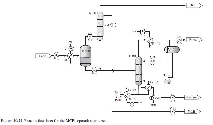
Figure 20.22 shows the monochlorobenzene separation process introduced in Section 7.4. The process involves a flash vessel,
Question:
Figure 20.22 shows the monochlorobenzene separation process introduced in Section 7.4. The process involves a flash vessel, V-100; an absorption column, T-100; a distillation column, T-101; a reflux drum, V-101; and three utility heat exchangers. As shown in Figure 20.22, most of the \(\mathrm{HCl}\) is removed at high purity in the vapor effluent of \(\mathrm{T}-100\). However, in contrast with the design shown in Chapter 7, the design in Figure 20.22 does not include a "treater" to remove the residual \(\mathrm{HCl}\); instead, it is purged in a small vapor overhead product stream in T-101. The benzene and monochlorobenzene are obtained at high purity as distillate and bottoms liquid products in T-101. Note that the 12 available control valves are identified. Your task is to design a conceptual control system to ensure that the process provides stable production at a desired level while meeting quality specifications.
Figure 20.22:-
Step by Step Answer:


Product And Process Design Principles Synthesis Analysis And Evaluation
ISBN: 9781119355243
4th Edition
Authors: Warren D. Seider, Daniel R. Lewin, J. D. Seader, Soemantri Widagdo, Rafiqul Gani, Ka Ming Ng
