

Question: Figure 20.25 shows the flowsheet for a process for the production of synthesis gas (a mixture of hydrogen, carbon monoxide, and carbon dioxide and a
Figure 20.25 shows the flowsheet for a process for the production of synthesis gas (a mixture of hydrogen, carbon monoxide, and carbon dioxide and a small quantity of unreacted residual methane) from methane, steam, and oxygen. The feed stream of methane is mixed with steam that is generated using waste heat generated in the process, heated in E-100 and then fed to the reformer R-100, where partial conversion of the methane to hydrogen and \(\mathrm{CO}\) takes place. The heat demanded by this endothermic reaction is provided by the combustion of fuel gas ( \(\mathrm{fg}\) ) in \(\mathrm{R}-100\). The hot reformer effluent stream first feeds E-100 to preheat the reformer feed as stated and is then further cooled in E-101, mixed with the oxygen feed stream, and then fed to the adiabatic oxidation reactor, \(\mathrm{R}-101\), where the remaining methane reacts to produce more hydrogen and \(\mathrm{CO}_{2}\). The effluent from R-101 is cooled in E-102 and then fed to the adiabatic shift reactor, \(\mathrm{R}-102\), where it is possible to control the ratio of \(\mathrm{CO}: \mathrm{CO}_{2}\) (depending on the feed temperature to R-102). The effluent stream from R-102 is cooled in E-103 and then fed to the flash vessel
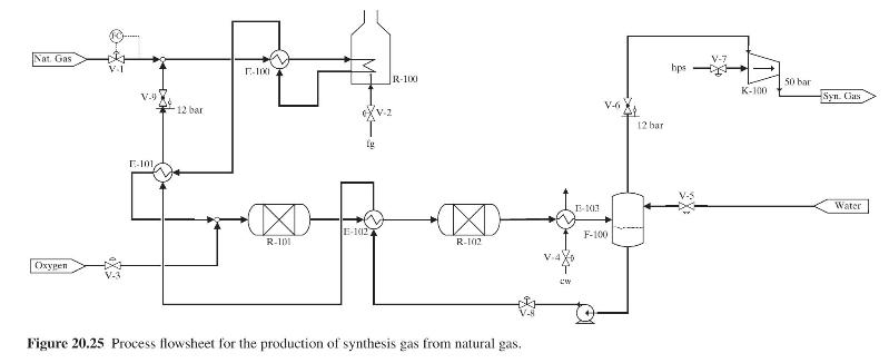
F-100, where the water in the synthesis gas condenses and is drawn off as the liquid effluent stream, which is recycled back to the process feed after being converted to saturated steam by heat exchange with hot process streams in E-102 and E-101. The vapor effluent from F-100 is compressed in K-100 to 50 bar and is the desired synthesis gas.
You are requested to suggest a plantwide control system to enable stable operation of the process in Figure 20.25 while satisfying the following requirements:
(a) Fixed feed methane consumption; thus, valve V-1 is already assigned to accomplish flow control of the methane feed stream as shown in Figure 20.25.
(b) Controlled hydrogen production rate in the reformer by regulation of the methane/steam ratio in the feed to R-100.
(c) Control of the \(\mathrm{H}_{2}: \mathrm{CO}_{2}\) ratio in the oxidation reactor (R-101) effluent.
(d) Control of the \(\mathrm{CO}: \mathrm{CO}_{2}\) ratio in the shift reactor (R-102) effluent.
(e) Minimization of the energy consumption in the reformer.
Figure 20.25:-

Nat Gas Oxygen V.9 12 bar E-101 E-100 V-2 R-100 V-6 E-102 R-101 R-102 Figure 20.25 Process flowsheet for the production of synthesis gas from natural gas. cw 13-103 F-100 12 bar hps K-100 50 bar Syn. Gas Water
Step by Step Solution
3.33 Rating (150 Votes )
There are 3 Steps involved in it

Get step-by-step solutions from verified subject matter experts