

Figure 20.28 shows the flowsheet for the HDA process for the production of benzene from toluene and
Question:
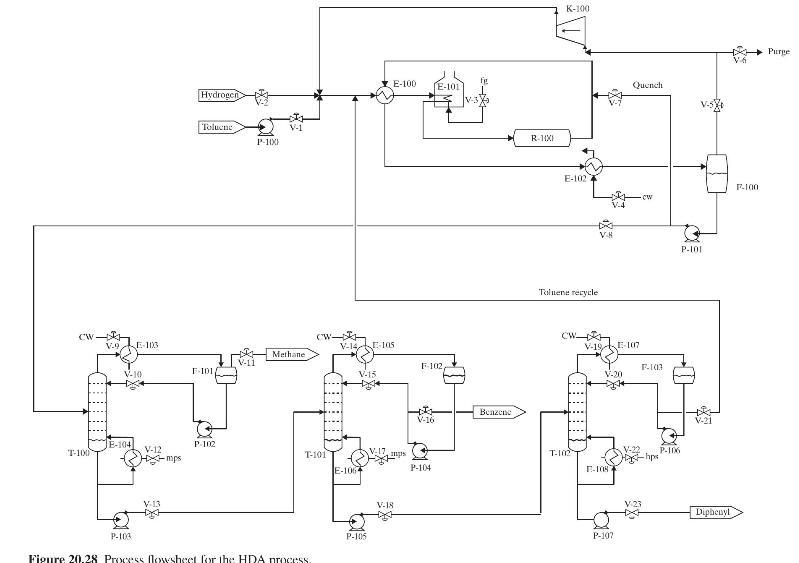
Figure 20.28 shows the flowsheet for the HDA process for the production of benzene from toluene and hydrogen. Feed streams of toluene (entering through valve V-1) and hydrogen (entering through valve \(\mathrm{V}-2\) ) are mixed with a liquid recycle stream rich in toluene and a vapor recycle stream rich in hydrogen, and the combined stream is preheated first in E-100, and then vaporized and superheated in furnace E-101. The vaporized mixture of toluene and hydrogen is fed to the adiabatic PFR, R-100, where they mostly undergo partial conversion to the desired main products, benzene and methane, as well a small portion to the undesired byproduct, diphenyl. The hot reactor effluent is cooled by heat exchange with the reactor feed in E-100 and then by cooling water in E-102 before being flashed in F-100. A portion of the hydrogen-rich vapor product stream from F-100 is purged through valve V-6 to attenuate the methane content and then compressed in K-100 and recycled. The compressor is operated at maximum capacity to enable production rate to be maximized. A portion of the liquid product stream from F-100 is recycled and mixed with the reactor effluent stream to cool it before it enters E-100, but most of it is fed to a separation system consisting of three columns in series.
In the first column, T-100, the reactor products are separated into a methane-rich distillate with the other components exiting as a feed stream to the second column, T-101, which produces a benzene-rich distillate and a mixture of toluene and diphenyl as bottoms. This is fed to the last column, T-102, which separates it into a toluene-rich distillate, which is recycled, and a bottoms stream consisting largely of diphenyl.
You are requested to suggest a plantwide control system to enable stable operation of the process, while regulating the production rate. Your solution should follow the procedure of Luyben et al. and should include the positioning of all control loops in the PFD of Figure 20.28. You are asked not to add control valves to those already in place in the PFD or any additional utility heaters and coolers.
Figure 20.28:-
Step by Step Answer:


Product And Process Design Principles Synthesis Analysis And Evaluation
ISBN: 9781119355243
4th Edition
Authors: Warren D. Seider, Daniel R. Lewin, J. D. Seader, Soemantri Widagdo, Rafiqul Gani, Ka Ming Ng
