

Question: For the datapath from Figure 4.24, draw the logic diagram for the part of the control unit that implements just the first signal. Assume that
For the datapath from Figure 4.24, draw the logic diagram for the part of the control unit that implements just the first signal. Assume that we only need to support LW, SW, BEQ, ADD, and J (jump) instructions.
Different instructions require different control signals to be asserted in the datapath. The remaining problems in this exercise refer to the following two control signals from Figure 4.24: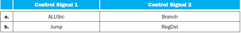
Figure 4.24![PC 4 Instruction [25-0] Add Read address Instruction [31-0] Instruction memory 26 Shift left 2 Instruction](https://dsd5zvtm8ll6.cloudfront.net/images/question_images/1698/2/2/1/8226538cefe791201698221821237.jpg)
a. b. Control Signal 1 ALUSrc Jump Control Signal 2 Branch RegDst
Step by Step Solution
3.51 Rating (154 Votes )
There are 3 Steps involved in it
Understanding the Problem Control Unit CU The CU is responsible for fetching instructions decoding them and generating control signals to coordinate t... View full answer

Get step-by-step solutions from verified subject matter experts