

Question: Let us assume that processor testing is done by illing the PC, registers, and data and instruction memories with some values (you can choose which
Let us assume that processor testing is done by illing the PC, registers, and data and instruction memories with some values (you can choose which values), letting a single instruction execute, then reading the PC, memories, and registers. These values are then examined to determine if a particular fault is present. Can you design a test (values for PC, memories, and registers) that would determine if there is a stuck-at-0 fault on this signal?
When silicon chips are fabricated, defects in materials (e.g., silicon) and manufacturing errors can result in defective circuits. A very common defect is for one wire to affect the signal in another. This is called a cross-talk fault. A special class of cross-talk faults is when a signal is connected to a wire that has a constant logical value (e.g., a power supply wire). In this case we have a stuck-at-0 or a stuck-at-1 fault, and the affected signal always has a logical value of 0 or 1, respectively.
The following problems refer to the following signal from Figure 4.24: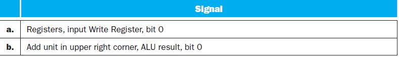
Figure 4.24![PC 4 Instruction [25-0] Add Read address Instruction [31-0] Instruction memory 26 Shift left 2, Instruction](https://dsd5zvtm8ll6.cloudfront.net/images/question_images/1698/2/2/0/7976538cafd628951698220795953.jpg)
a. Registers, input Write Register, bit 0 b. Signal Add unit in upper right corner, ALU result, bit 0
Step by Step Solution
3.54 Rating (154 Votes )
There are 3 Steps involved in it
To design a test for a stuckat0 fault on the signal described in the problem we need to ensure that ... View full answer

Get step-by-step solutions from verified subject matter experts