New Semester
Started
Get
50% OFF
Study Help!
--h --m --s
Claim Now
Question Answers
Textbooks
Find textbooks, questions and answers
Oops, something went wrong!
Change your search query and then try again
S
Books
FREE
Study Help
Expert Questions
Accounting
General Management
Mathematics
Finance
Organizational Behaviour
Law
Physics
Operating System
Management Leadership
Sociology
Programming
Marketing
Database
Computer Network
Economics
Textbooks Solutions
Accounting
Managerial Accounting
Management Leadership
Cost Accounting
Statistics
Business Law
Corporate Finance
Finance
Economics
Auditing
Tutors
Online Tutors
Find a Tutor
Hire a Tutor
Become a Tutor
AI Tutor
AI Study Planner
NEW
Sell Books
Search
Search
Sign In
Register
study help
computer science
essentials of computer organization
Essentials Of Computer Organization And Architecture 5th Edition Linda Null, Julia Lobur - Solutions
66. Complete the truth table for the following sequential circuit: Next State S X Y 0 0 ON S 0 0 1 Full-Adder D Q Z >C 0 1 0 Q' 0 1 1 1 0 0 1 0 1 1 1 0 1 1 1 Q
68. True or false: When a JK flip-flop is constructed from an SR flip-flop, S = JQ′ and R = KQ.
70. A Null-Lobur flip-flop (NL flip-flop) behaves as follows: If N =0, the flip-flop does not change state. If N = 1, the next state of the flip-flop is equal to the value of L.a) Derive the characteristic table for the NL flip-flop.b) Show how an SR flip-flop can be converted to an NL flipflop by
71. A Mux-Not flip-flop (MN flip-flop) behaves as follows: If M =the flip-flop complements the current state. If M = 0, the next state of the flip-flop is equal to the value of N.a) Derive the characteristic table for the flip-flop.b) Show how a JK flip-flop can be converted to an MN flipflop by
72. List the steps necessary to read a word from memory in the 4 × 3 memory circuit shown in Figure 3.41.
73. Construct Moore and Mealy machines that complement their input.
74. Construct a Moore machine that counts modulo 5.
75. Construct two parity checkers using a Moore machine for one and a Mealy machine for the other.
77. Using the convolutional code and Viterbi algorithm described in this chapter, assuming that the encoder and decoder always start in State 0, determine the following:a) The output string generated for the input: 10010110.b) In which state is the encoder after the sequence in Part a is read?c)
78. Repeat question 65 to determine the following:a) The output string generated for the input: 00101101.b) In which state is the encoder after the sequence in Part a is written?c) Which bit is in error in the string, 00 01 10 11 00 11 00?What is the probable value of the string?
79. Repeat question 65 to determine the following:a) The output string generated for the input: 10101010.b) In which state is the encoder after the sequence in Part a is written?c) Which bit is in error in the string, 11 10 01 00 00 11 01?What is the probable value of the string?
80. Repeat question 65 to determine the following:a) The output string generated for the input: 01000111.b) In which state is the encoder after the sequence in Part a is written?c) Which bit is in error in the string, 11 01 10 11 01 00 01?What is the probable value of the string?
1. What is the function of a CPU?
2. What purpose does a datapath serve?
3. What does the control unit do?
5. How does the ALU know which function to perform?
6. Why is a bus often a communications bottleneck?
8. Why is a bus protocol important?
10. What is a bus cycle?
11. Name three different types of buses and where you would find them.
12. What is the difference between synchronous buses and nonsynchronous buses?
13. What are the four types of bus arbitration?
14. Explain the difference between clock cycles and clock frequency.
15. How do system clocks and bus clocks differ?
16. What is the function of an I/O interface?
17. Explain the difference between memory-mapped I/O and instruction-based I/O.
18. What is the difference between a byte and a word? What distinguishes each?
19. Explain the difference between byte addressable and word addressable.
20. Why is address alignment important?
21. List and explain the two types of memory interleaving and the differences between them.
22. Describe how an interrupt works, and name four different types.
23. How does a maskable interrupt differ from a nonmaskable interrupt?
24. Why is it that if MARIE has 4K words of main memory, addresses must have 12 bits?
25. Explain the functions of all of MARIE’s registers.
26. What is an opcode?
27. Explain how each instruction in MARIE works.
29. What is the significance of RTN?
30. Is a microoperation the same thing as a machine instruction?
How does interrupt-driven I/O work?
35. What is an embedded system? How does it differ from a regular computer?
36. Provide a trace (similar to the one in Figure 4.14) for Example 4.1.
37. Explain the difference between hardwired control and microprogrammed control.
38. What is a stack? Why is it important for programming?
39. Compare CISC machines to RISC machines.
40. How does Intel’s architecture differ from MIPS?
41. Name four Intel processors and four MIPS processors.
1. What are the main functions of the CPU?
2. How is the ALU related to the CPU? What are its main functions?
7. Redo Example 4.1 using high-order interleaving instead of low-order interleaving.
8. Suppose we have four memory modules instead of eight in Figures 4.6 and 4.7. Draw the memory modules with the addresses they contain using:a) high-order interleavingb) low-order interleaving
10. Suppose that a 2M × 16 main memory is built using 256K × 8 RAM chips and that memory is word addressable.a) How many RAM chips are necessary?b) If we were accessing one full word, how many chips would be involved?3.c) How many address bits are needed for each RAM chip?4.d) How many banks will
11. Redo exercise 10 assuming a 16M × 16 memory built using 512K × 8 RAM chips.
12. 12. Suppose we have 1G × 16 RAM chips that make up a 32G × 64 memory that uses high interleaving. (Note: This means that each word is 64 bits in size and there are 32G of these words.)1.a) How many RAM chips are necessary?2.b) Assuming four chips per bank, how many banks are required?3.c) How
13. 13. A digital computer has a memory unit with 24 bits per word.The instruction set consists of 150 different operations. All instructions have an operation code part (opcode) and an address part (allowing for only one address). Each instruction is stored in one word of memory.1.a) How many bits
15. 15. Assume a 2 byte memory.1. ◆a) What are the lowest and highest addresses if memory is byte addressable?2. ◆b) What are the lowest and highest addresses if memory is word addressable, assuming a 16-bit word?3.c) What are the lowest and highest addresses if memory is word addressable,
16. 16. Suppose the RAM for a certain computer has 256M words, where each word is 16 bits long.1.a) What is the capacity of this memory expressed in bytes?2.b) If this RAM is byte addressable, how many bits must an address contain?3.c) If this RAM is word addressable, how many bits must an address
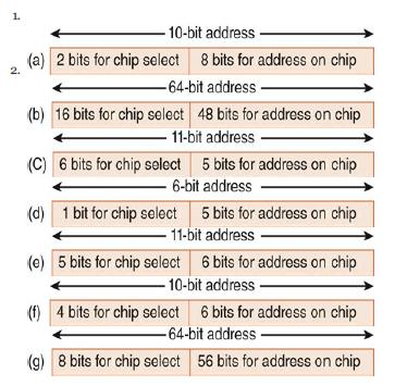
18. 18. Given a memory of 2048 bytes consisting of several 64 × 8 RAM chips, and assuming byte-addressable memory, which of the following seven diagrams indicates the correct way to use the address bits? Explain your answer. 2. 1. -10-bit address (a) 2 bits for chip select 8 bits for address on
19. 19. Explain the steps in the fetch–decode–execute cycle. Your explanation should include what is happening in the various registers.
20. 20. Combine the flowcharts that appear in Figures 4.11 and 4.12 so that the interrupt checking appears at a suitable place.
21. 21. Explain why, in MARIE, the MAR is only 12 bits wide and the AC is 16 bits wide. (Hint: Consider the difference between data and addresses.)
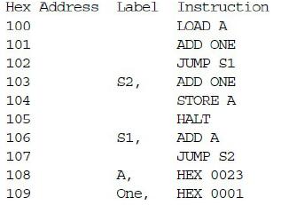
22. 22. List the hexadecimal code for the following program (handassemble it). Hex Address Label Instruction 100 LOAD A 101 ADD ONE 102 JUMP S1 103 S2, ADD ONE 104 STORE A 105 HALT 106 S1, ADD A 107 JUMP S2 108 A, HEX 0023 109 One, HEX 0001
23. What are the contents of the symbol table for the preceding program?
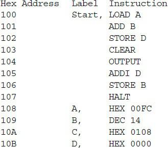
24. 24. Consider the MARIE program below.1.a) List the hexadecimal code for each instruction.2.b) Draw the symbol table.3.c) What is the value stored in the AC when the program terminates? Hex Address Label Instruction 100 Start, LOAD A 101 102 103 104 105 106 107 ADD B STORE D CLEAR OUTPUT ADDI D
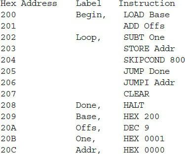
25. Consider the MARIE program below.1.a) List the hexadecimal code for each instruction.2.b) Draw the symbol table.3.c) What is the value stored in the AC when the program terminates? Hex Address Label Instruction 200 Begin, LOAD Base 201 ADD Offs 202 Loop, SUBT One 203 STORE Addr 204 SKIPCOND 800
26. Given the instruction set for MARIE in this chapter, do the following.Decipher the following MARIE machine language instructions(write the assembly language equivalent):1. ◆a) 0010000000000111 2.b) 1001000000001011 3.c) 0011000000001001
27. 27. Write the assembly language equivalent of the following MARIE machine language instructions:1.a) 0111000000000000 2.b) 1011001100110000 3.c) 0100111101001111
28. 28. Write the assembly language equivalent of the following MARIE machine language instructions:1.a) 0000010111000000 2.b) 0001101110010010 3.c) 1100100101101011
29. Write the following code segment in MARIE’s assembly language..
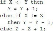
30. Write the following code segment in MARIE’s assembly language: if x
32. Write a MARIE program to evaluate the expression A × B + C× D.
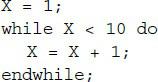
33. 33. Write the following code segment in MARIE assembly language: = 1; while X < 10 do X = X + 1; endwhile;
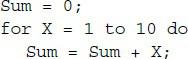
34. Write the following code segment in MARIE assembly language. (Hint: Turn the for loop into a while loop.) Sum = 0 ; for X = 1 to 10 do Sum Sum + X;
36. Write a MARIE subroutine to subtract two numbers.
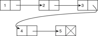
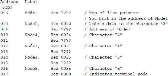
37. A linked list is a linear data structure consisting of a set of nodes, where each one except the last points to the next node in the list. (Appendix A provides more information about linked lists.)Suppose we have the set of five nodes shown in the illustration below. These nodes have been
39. 39. MARIE saves the return address for a subroutine in memory, at a location designated by the JnS instruction. In some architectures, this address is stored in a register, and in many it is stored on a stack. Which of these methods would best handle recursion? Explain your answer. (Hint:
40. 40. Write a MARIE program that performs the three basic stack operations: push, peek, and pop (in that order). In the peek operation, output the value that’s on the top of the stack. (If you are unfamiliar with stacks, see Appendix A for more information.)
Provide a trace (similar to the one in Figure 4.14) for Example 4.3.
Provide a trace (similar to the one in Figure 4.14) for Example 4.4.
43. 43. Suppose we add the following instruction to MARIE’s ISA:IncSZ Operand This instruction increments the value with effective address “Operand,” and if this newly incremented value is equal to 0, the program counter is incremented by 1. Basically, we are incrementing the operand, and if
Suppose we add the following instruction to MARIE’s ISA:JumpOffset: X This instruction will jump to the address calculated by adding the given address, X, to the contents of the accumulator. Show how this instruction would be executed using RTN.
Suppose we add the following instruction to MARIE’s ISA:JumpI0ffset X This instruction will jump to the address calculated by going to address X, then adding the value found there to the value in the AC.Show how this instruction would be executed using RTN.
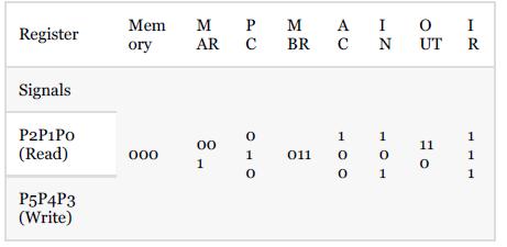
The table below provides a summary of MARIE’s datapath control signals. Using this information, Table 4.9, and Figure 4.20 as guides, draw the control logic for MARIE’s Load instruction. Mem M PMA Register ory AR BR C Signals P2P1Po (Read) 000 1 8- 00 P5P4P3 (Write) IOI N UT R OTO 1 1 011 0 1
48. The table in Exercise 47 provides a summary of MARIE’s datapath control signals. Using this information, Table 4.9, and Figure 4.20 as guides, draw the control logic for MARIE’s JumpI instruction.
49. 49. The table in Exercise 47 provides a summary of MARIE’s datapath control signals. Using this information, Table 4.9, and Figure 4.20 as guides, draw the control logic for MARIE’s StoreI instruction.
52. 52. Building on the idea presented in Exercise 51, suppose that MARIE has a hardwired control unit and we decide to add a new instruction that requires eight clock cycles to execute. (This is one cycle longer than the longest instruction, JnS.) Briefly discuss the changes that we would need to
Using the coding given in Table 4.9, translate into binary the mnemonic microcode instructions given in Figure 4.23 for the fetch–decode cycle (the first nine lines of the table).
Continuing from Exercise 56, write the microcode for the jump table for the MARIE instructions for Jump X, Clear, and AddI X.(Use all ones for the Destination value.)
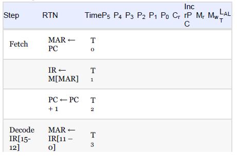
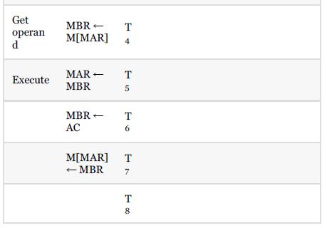
63. Which control signals should contain a one for each step in executing the StoreI instruction? Inc Step RTN TimeP5 P4 P3 P2 P1 Po Cr rP Mr MwLAL T MAR- T Fetch PC 0 IR T M[MAR] 1 PC PC +1 Decode IR[15- MAR IR[11- 12] 0] T 2 T 13 C
64. The PC ← PC + 1 microoperation is executed at the end of every fetch cycle (to prepare for the next instruction to be fetched).However, if we execute a Jump or a JumpI instruction, the PC overwrites the value in the PC with a new one, thus voiding out the microoperation that incremented the
65. 65. Write a MARIE program to allow the user to input eight integers (positive, negative, or zero) and then find the smallest and the largest and print each of these out.
66. 66. Write a MARIE program to sum the numbers 1 + 2 + 3 + 4 +… + N, where the user inputs N, and print the result.
67. 67. Write a MARIE subroutine that will multiply two numbers by using repeated addition. For example, to multiply 2 × 8, the program would add 8 to itself twice. (If the larger of the two numbers is chosen to be added to itself, the subroutine will run more quickly.)
68. 68. Write a MARIE program to raise an integer to a given power, using the subroutine written in problem 67.
1. If a computer uses hardwired control, the microprogram determines the instruction set for the machine. This instruction set can never be changed unless the architecture is redesigned.
2. A branch instruction changes the flow of information by changing the PC.
3. Registers are storage locations within the CPU itself.
4. A two-pass assembler generally creates a symbol table during the first pass and finishes the complete translation from assembly language to machine instructions on the second.
5. The MAR, MBR, PC, and IR registers in MARIE can be used to hold arbitrary data values.
6. MARIE has a common bus scheme, which means that a number of entities share the bus.
7. An assembler is a program that accepts a symbolic language program and produces the binary machine language equivalent, resulting in a one-to-one correspondence between the assembly language source program and the machine language object program.
Showing 500 - 600
of 1321
1
2
3
4
5
6
7
8
9
10
11
12
13
14
Step by Step Answers