New Semester
Started
Get
50% OFF
Study Help!
--h --m --s
Claim Now
Question Answers
Textbooks
Find textbooks, questions and answers
Oops, something went wrong!
Change your search query and then try again
S
Books
FREE
Study Help
Expert Questions
Accounting
General Management
Mathematics
Finance
Organizational Behaviour
Law
Physics
Operating System
Management Leadership
Sociology
Programming
Marketing
Database
Computer Network
Economics
Textbooks Solutions
Accounting
Managerial Accounting
Management Leadership
Cost Accounting
Statistics
Business Law
Corporate Finance
Finance
Economics
Auditing
Tutors
Online Tutors
Find a Tutor
Hire a Tutor
Become a Tutor
AI Tutor
AI Study Planner
NEW
Sell Books
Search
Search
Sign In
Register
study help
computer science
systems analysis design
C# Programming From Problem Analysis To Program Design 4th Edition Barbara Doyle - Solutions
Button objects are added to your form to add functionality. Users can click Button objects to perform a specific task. In addition to the inherited members, they have their own unique properties, methods, and events.
One of the differences between a console application and a Windows application is:a. Classes can only be used with console applications.b. One font size is used with console applications.c. Variables must be declared with console applications.d. Windows applications require that program statements
Which namespace includes most of the Control classes for developing Windows applications?a. Systemb. System.Windows.Controlsc. System.Windows.Components.Formsd. System.Windows.Formse. System.Windows.Drawing
Which of the following inherits members from the Control class?a. Labelb. Formc. TextBoxd. a and ce. all of the above
The is the front end of a program that represents the presentation layer or the visual image of the program.a. interfaceb. controlc. Visual Studiod. IDEe. framework
A(n) is a notification from the operating system that an action has occurred, such as the user clicking the mouse or pressing a key.a. method callb. statementc. eventd. GUIe. handler
Which of the Control objects is viewed as a container that can hold other objects when you design a Windows application?a. Controlb. Buttonc. Windowd. Framee. Form
Which property is used to set the caption for the Windows title bar?a. Captionb. Textc. Titled. TitleBare. WindowTitle
The class heading public class AForm : Form indicates that:a. Form is a derived class of the AForm class.b. AForm is the base class for the Form class.c. The class being defined is identified as Form.d. AForm inherits the members of the Form class.e. none of the above
If the name of the class is GraphicalForm, the following:public GraphicalForm( ) is an example of a(n):a. accessor methodb. propertyc. constructord. mutator methode. data member
You would use an IDE such as Visual Studio to construct Windows applications because it has the following capability:a. drag-and-drop constructionb. IntelliSense featuresc. access to the Properties window listing properties and eventsd. access to the Toolbox for dropping controlse. all of the above
Click is an example of a(n):a. eventb. propertyc. methodd. controle. handler
Visual Studio has a number of windows that can be viewed during design.The window used to hold controls that are dragged and dropped during construction is called the:a. Propertyb. Code Editorc. Form Designerd. Solution Explorere. Class View
If the System.Windows.Forms namespace is imported, the following statement:this.textbox1 = new System.Windows.Forms.TextBox( );can be written as:a. this.textbox1 = new TextBox( );b. textbox1 = new TextBox( );c. textbox1 = new System.Windows.Forms.TextBox( );d. all of the abovee. none of the above
The statement that actually constructs or instantiates a Button object is:a. this.button1 = new System.Windows.Forms.Button( );b. private System.Windows.Forms.Button button1;c. this.Controls.AddRange(this.button1);d. button1.Name = "A button";e. button1.Click += new
Create the higher/lower guessing game using a graphical user interface. Allow users to keep guessing until they guess the number. Keep a count of the number of guesses. Choose two colors for your game: one should be used to indicate that the value the users guessed is higher than the target; the
The index (or subscript) references the location of the variable relative to the beginning location.
How many components are allocated by the following statement?double [ ] values = new double [3];a. 32b. 3c. 2d. 4e. none of the above
What output is produced by the following code?int i;int [ ] anArray = new int [5];for (i = 0; i < anArray.Length; i++)anArray [i] = 2 * i;for (i = 0; i < anArray.Length; i++)Console.Write(anArray [i] + " ");a. 2 2 2 2 2b. 2 4 6 8 10c. 0 2 4 6 8 10d. 0 2 4 6 8e. none of the above
If you declare an array as int [ ] anArray = new int [5];you can double the value stored in anArray [2] with the statement:a. anArray [2] = anArray [5] * 2;b. anArray = anArray * 2;c. anArray [2] *= anArray [2] * 2;d. anArray [2] *= 2;e. none of the above
With the following declaration:int [ ] points = {550, 700, 900, 800, 100};The statement points [3] = points [3] + 10; willa. replace the 800 amount with 810b. replace the 550 amount with 560c. replace the 900 amount with 910d. result in an errore. none of the above
With the following declaration:int [ ] points = {300, 100, 200, 400, 600};The statement points [4] = points [4-2]; willa. replace the 400 amount with 2b. replace the 300 and 600 with 2c. replace the 600 with 200d. result in an errore. none of the above
With the following declaration:int [ ] points = {300, 100, 200, 400, 600};The statement Console.Write(points [2] + points [3]); willa. display 200400b. display 600c. display "points[2] + points[3]"d. result in an errore. none of the above
When you pass a single integer array element to a method, the method receives:a. a copy of the arrayb. the address of the arrayc. a copy of the value in the elementd. the address of the elemente. none of the above
When you pass the entire array to a method, the method receives:a. a copy of the arrayb. the address of the arrayc. a copy of the first value in the arrayd. the address of each of the elements in the arraye. none of the above
Which method in the Array class can be used to return the index of the first occurrence of a value in a one-dimensional array?a. IndexOf( )b. LastIndex( )c. FirstIndex( )d. Search( )e. none of the above
A correct method call to a method that has the following heading would be:int result(int[ ] anArray, int num)a. Console.Write(result(anArray, 3));b. result(anArray, 30);c. Console.Write(result(anArray[ ], 3));d. result(anArray[ ], 30);e. none of the above
With arrays a limitation on the foreach statement is that it can:a. only be used for read-only accessb. only be used with integral type arraysc. not be nestedd. only be used with arrays smaller than 1000 elementse. not be used with dynamic arrays
A valid call to the following method using a params parameter is:public static void DoSomething(params int[ ] item)a. DoSomething(4);b. DoSomething(anArray);c. DoSomething(4, 5, 6);d. a and c are correcte. all are correct
Using the following declaration:int [ ] anArray = {34, 55, 67, 89, 99};What would be the result of each of the following output statements?a. Console.WriteLine(anArray.Length);b. Console.WriteLine(anArray[2]);c. Console.WriteLine(anArray[anArray.Length -2]);d. Console.WriteLine(anArray[2 + 1] *
Using the following declarations, write solutions for Steps a through e:int [ ] bArray = new int [10];a. Write a foreach loop to display the contents of bArray.b. Write a for loop to increment each element in bArray by 5.c. Use a member of the Array class to locate the index in the bArray array
Create array declarations for the following problem specifications.a. An array to hold the names of five font strings. Initialize the array with your favorites.b. An array to hold 12 state names. Initialize with the 12 states closest to your campus.c. An array to hold the 10 most common single
Explain the difference between the pass by reference and pass by value. When an array is sent to a method, which one is used?
Write a program that reads data into an array of type int. Valid values are from 0 to 10.Your program should display how many valid values were inputted as well as the number of invalid entries. Output a list of distinct valid entries and a count of how many times that entry occurred.Use the
Which of the following adds 42 to the element at the fifth physical spot?int [ ] x = {12, 13, 14, 15, 16, 17, 18, 19};a. x[5] += 42;b. x[4] += 42;c. x[5 + 42];d. x = 42 + 5;e. none of the above
Using the following declaration:int [ ] x = {12, 13, 14, 15, 16, 17, 18, 19};What does x[8] refer to?a. 19b. 18c. '\0'd. 0e. none of the above
An array is a list of data items that .a. all have the same typeb. all have different namesc. all are integersd. all are originally set to null ('\0')e. none of the above
With C#, the size or length of the array cannot change after it is allocated, but you can use a variable to declare the size of an array.
During the declaration, specify the number of individual elements for which space must be allocated and use an identifier representative of the contents(normally a singular name).
When you use an array as a method parameter, the array identifier and type are specified; however, the length or size of the array is not included. Opening and closing square brackets are required.
The call to that method includes the name of the array only.
Array class has a number of predefined methods that perform sort, binary search, copy, and reverse. All arrays, of any type, inherit them.
Include params with a parameter to indicate that the number of arguments may vary.
Within the foreach statement, an identifier represents the array element for the iteration currently being performed.
The type used in the foreach expression must match the array type.
Arrays can be sent as arguments to methods, and in addition, a method can have an array as its return type.
Array objects and string types are references instead of value types.
The value contained within the square brackets that is used to indicate the length of the array must be a(n):a. classb. doublec. stringd. integere. none of the above
Which of the following array declarations would enable you to store the high temperature for each day of one full week?a. int temp1, temp2, temp3, temp4, temp5, temp6, temp7;b. int temp [7] = new int [7];c. temp int [ ] = new temp[7];d. int [ ] temp = new int [7];e. int [ ] temp = new temp [8];
Assume an array called num is declared to store four elements. Which of the following statements correctly assigns the value 100 to each of the elements?a. for(x = 0; x < 3; ++x) num [x] = 100;b. for(x = 0; x < 4; ++x) num [x] = 100;c. for(x = 1; x < 4; ++x) num [x] = 100;d. for(x = 1; x < 5; ++x)
Choose the statement that does not apply to the following declaration:double [ ] totalCostOfItems = {109.95, 169.95, 1.50, 89.95};a. declares a one-dimensional array of floating-point valuesb. specifies the size of the array as fivec. sets the array element totalCostOfItems [1] to 169.95d. declares
What value is returned by the method named result?int result(int[ ] anArray, int num){int i, r;for (r = 0, i = 1; i < num; ++i)if (anArray[i] > anArray [r] )r = i;return (r);}a. the index of the largest of the first num elements of array anArrayb. the value of the largest of the first num elements
What is the effect of the following program segment?int[ ] anArray = new int[50];int i, j, temp;string inValue;for (i = 0; i < 50; ++i){Console.Write("Enter Value");inValue = Console.ReadLine( );anArray[i] = int.Parse(inValue);}temp = 0;for (i = 1; i < 50; ++i)if (anArray[i] < anArray[0])++temp;a.
Using the following declaration:char [ ] n = {'a', 'b', 'c', 'd', 'e'};What does n[1] refer to?a. ab. abcdec. bd. 'a'e. none of the above
The Ion Realty Sales Corporation would like to have a listing of their sales over the past few months. Write a program that accepts any number of monthly sales amounts. Display the total of the values. Display a report showing each original value entered and the percentage that value contributes to
Write a temperature application. Your solution should be a two class application that has a one-dimensional array as a data member. The array stores temperatures for any given week. Provide constructors for instantiating the class and methods to return the highest temperature, lowest temperature,
The Hashtable class represents a collection of key/value pairs that are organized based on the hash code of the key. Override the GetHashCode( )method to provide a new algorithm for the hash function.
BitArrays are very useful for working with large data sets. They are most commonly used to represent a simple group of Boolean flags.
The Queue class represents a First In First Out (FIFO) collection of objects. The Enqueue( ) method adds an object to the end of the queue.Dequeue( ) removes and returns the object at the beginning of the queue.
The Stack class represents a simple last-in-first-out (LIFO) collection of objects. The Push( ) method adds an object to the end of the stack. Pop( )removes and returns the object at the beginning of the stack.
When three values are contained within the square brackets, the last number represents the number of:a. classesb. rowsc. planesd. columnse. none of the above
Which of the following array declarations would enable you to store the high and low temperatures for each day of one full week?a. int temp1Lo, temp2Lo, temp3Lo, temp4Lo, temp5Lo, temp6Lo, temp7Lo, temp1Hi, temp2Hi, temp3Hi, temp4Hi, temp5Hi, temp6Hi, temp7Hi;b. int temp [7, 2] = new int [7, 2];c.
Assume a two-dimensional array called num is declared to hold four rows and seven columns. Which of the following statements correctly assigns the value 100 to the third physical column of each row?a. for (x = 0; x < 3; ++x) num [x, 2] = 100b. for (x = 0; x < 4; ++x) num [x, 2] = 100;c. for (x = 1;
Choose the statement that does not apply to the following declaration:double [ , ] totalCostOfItems ={{109.95, 169.95, 1.50, 89.95}{27.9, 18.6, 26.8, 98.5}};a. declares a two-dimensional array of floating-point valuesb. establishes the maximum number of rows as 4c. sets the array element
What value is returned by the method named result?int result(int [ , ] anArray){int j = 0, i = 0;for (int r = 0; r < anArray.GetLength(0); r++)for (int c = 0; c < anArray.GetLength(1); c++)if (anArray[r, c] < anArray[i, j]){i = r;j = c;}return i;}a. the row index of the largest element of array
What is the largest dimension an array can be declared to store values?a. 10b. 100c. 3d. 5e. there is no limit
Using the following declaration:char [ , ] n = {{'a', 'b', 'c', 'd', 'e'},{'f', 'g', 'h', 'i', 'j'}};What does n[1, 1] refer to?a. ab. fc. bd. ge. none of the above
A two-dimensional array is a list of data items that .a. all have the same typeb. all have different namesc. all are integersd. all are originally set to null ('\0')e. none of the above
Using the following declaration:int [, ] x = {{12, 13, 14, 15 }, {16, 17, 18, 19 }};What does x[2, 4] refer to?a. 19b. 18c. '\0'd. 0e. none of the above
Which of the following adds 95 to the array element that is currently storing 14?int [, , ] x = {{12, 13 }, {14, 15 }, {16, 17 }, {18, 19 }};a. x[2] += 95;b. x[1, 0] += 95;c. x[1, 0 += 95];d. x = 14 + 95;e. none of the above
How many components are allocated by the following statement?double [, ] values = new double [3, 2];a. 32b. 3c. 5d. 6e. none of the above
Given the declaration for values in number 11 above, how would you store 0 in the last physical location?a. values = 0;b. values[6] = 0;c. values[3, 2] = 0;d. values[2, 1] = 0;e. none of the above
If you declare an array as int [, ] anArray = new int [5, 3]; you can double the value stored in anArray[2, 1] with the statement:a. anArray[2, 1] = anArray[5, 1] * 2;b. anArray = anArray * 2;c. anArray[2, 1] *= anArray[2, 1] * 2;d. anArray[2, 1] *= 2;e. none of the above
String variables are objects of the string class; thus, a number of predefined methods including the following can be used: Trim( ), ToUpper( ), ToLower( ), Substring( ), Split( ), Replace( ), Insert( ), and Copy( ).
The string type is an alias for the System.String class in the .NET Framework. You can access the individual characters using an index, with the first index being zero.
The string class stores an immutable series of characters. After you give a string a value, it cannot be modified.
Create three arrays of type double. Do a compile-time initialization and place different values in two of the arrays. Write a program to store the product of the two arrays in the third array. Produce a display using the MessageBox class that shows the contents of all three arrays using a single
Write a program that allows the user to enter any number of names, last name first. Using one of the predefined methods of the Array class, order the names in ascending order. Display the results.
Write a two class application that has as a data member an array that can store state area codes. The class should have a member method that enables users to test an area code to determine if the number is one of the area codes in the state exchange.The member method should use one of the
Write an application that allows the user to input monthly rainfall amounts for one year. Calculate and display the average rainfall for the year. Display the month name along with the rainfall amount and its variance from the mean.
Write a program that accepts any number of homework scores ranging in value from 0 through 10.Prompt the user for a new score if they enter a value outside of the specified range. Prompt the user for a new value if they enter an alphabetic character. Store the values in an array. Calculate the
Write a program that allows any number of values between 0 and 10 to be entered. When the user stops entering values, display a frequency distribution bar chart. Use asterisks to show the number of times each value was entered. If a given number is not entered, no asterisks should appear on that
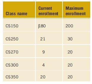
Write a two class solution that includes data members for the name of the course, current enrollment, and maximum enrollment. Include an instance method that returns the number of students that can still enroll in the course.The ToString( ) method should return the name of the course, current
Two-dimensional and multidimensional arrays may contain any number of variables of the same type. One common identifier names the entire structure.
Two-dimensional and multidimensional arrays should be named using singular nouns.
To access a two-dimensional or multidimensional array element, use the number of indexes included in the declaration. Indexes are separated by commas and enclosed in square brackets.
When you use a two-dimensional or multidimensional array as a method parameter, the array identifier and type are specified; however, the length or size of the array is not included. Opening, closing square brackets, and commas are required. The call to that method includes the name of the array
Two-dimensional and multidimensional arrays can be sent as arguments to methods, and in addition, a method can have a two-dimensional or multidimensional array as its return type. The square bracket that is included before the name of the method is empty with the exception of one or more commas.The
Two-dimensional and other multidimensional arrays follow the same guidelines as one-dimensional arrays.
A two-dimensional array is usually visualized as a table divided into rows and columns. The first index represents the number of rows.
When the number of columns in rows may need to differ, a jagged, or ragged array, can be used. It is called an ‘‘array of arrays.’’
ArrayList class creates a listlike structure that can dynamically increase or decrease in length. Like traditional arrays, indexes of ArrayList objects are zero based. A number of predefined methods are included.
To create a multidimensional array, specify the type and the number of dimensions per rank. These values are separated by commas. A threedimensional array would be defined with type [ , , ] identifier = new type [length_of_planes, length_of_rows, length_of_columns].
With the following declaration:int [ , ] points = {{300, 100, 200, 400, 600},{550, 700, 900, 800, 100}};The statement points[1, 3] = points[1, 3] + 10; willa. replace the 300 amount with 310 and 900 with 910b. replace the 500 amount with 510c. replace the 900 amount with 910d. replace the 800
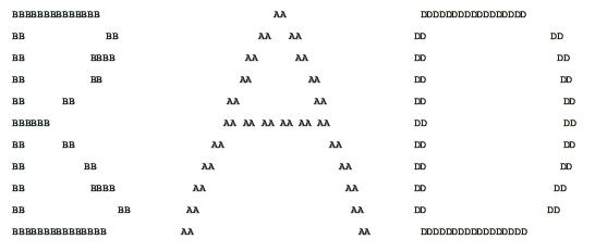
Write your initials in block characters to a standard output device. Design your prototype using the symbol(s) of your choice. For example, my initials in block characters are shown below. BBBBBBBBBBBBBB BB BB BBBB BB BB BB BBBBBB BB BB BB AA BB M BB BB BB BBBB BB BB BBBBBBBBBBBBBBB MA
Create an application that displays the following patterns. You may use any character of your choice to construct the pattern. One possible solution follows. ***** *** * ** *** * * *** ***** *
Hangman is a favorite childhood game. Design the stick figure for this game and produce a printed listing with your stickman. One possible design follows. You may implement this design or develop an improved version. (^;^) ./ | \.
Produce a listing containing information about you. Include items such as, your name, hometown, major, hobby and/or favorite activity. Label each piece of information, place each of the items on separate lines and place a backslash (\) after each entry. Begin and end the entire listing with the
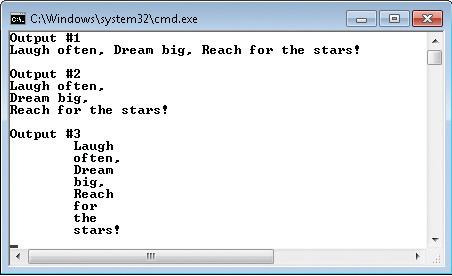
Create an application that produces three different outputs using the same phrase. Select your own favorite popular saying for the phrase. The phrase should first be displayed on one line. Use at least three Write( ) methods - but the output should all appear on a single line.Then print the phrase
Flags are a symbol of unity and invoke special meaning to their followers.Create a design for a flag, and write a program that displays your design. One possible design
Showing 1000 - 1100
of 5433
First
4
5
6
7
8
9
10
11
12
13
14
15
16
17
18
Last
Step by Step Answers