New Semester
Started
Get
50% OFF
Study Help!
--h --m --s
Claim Now
Question Answers
Textbooks
Find textbooks, questions and answers
Oops, something went wrong!
Change your search query and then try again
S
Books
FREE
Study Help
Expert Questions
Accounting
General Management
Mathematics
Finance
Organizational Behaviour
Law
Physics
Operating System
Management Leadership
Sociology
Programming
Marketing
Database
Computer Network
Economics
Textbooks Solutions
Accounting
Managerial Accounting
Management Leadership
Cost Accounting
Statistics
Business Law
Corporate Finance
Finance
Economics
Auditing
Tutors
Online Tutors
Find a Tutor
Hire a Tutor
Become a Tutor
AI Tutor
AI Study Planner
NEW
Sell Books
Search
Search
Sign In
Register
study help
computer science
systems analysis design
System Engineering Analysis Design And Development Concepts Principles And Practices Wiley Series In Systems Engineering And Management 2nd Edition Charles S. Wasson - Solutions
Describe the evolution of specifications from initial System Concept to SPS.
What are the basic types of specifications?
How does each type of specification apply to system development?
What is a Specification Tree and how is it structured?
Who “owns” a specification and what is their authority to implement changes?
What is the generalized format for most specifications?
What is a requirement?
What is a source or originating requirement?
What is a stakeholder requirement?
What is an objective requirement?
What is a threshold requirement?
What are the categories of specification requirements?
What are operational requirements?
What are capability requirements?
What are design requirements?
What are interface requirements?
What are verification requirements?
What are validation requirements?
What are requirement priorities?
What are the four types of operational requirements?
What are four common problems with requirements?
What are some common approaches to developing specifications?
What is the “feature-based” specification development approach?
What is the “performance-based” specification development approach?
What is the “reuse” specification development approach?
What is the “capability architecture-based” specification development approach?
Compare and contrast the four specification development approaches.
How are specification reviews performed?
How do you know when a specification is ready for release?
What is requirements derivation?
How do you derive requirements?
What is requirements allocation?
How do you allocate requirements?
What is requirements flow down?
How do you flow down requirements?
What is requirements traceability?
How do you trace requirements? To where?
What is the relationship between MOEs, MOSs, MOPs, and TPMs?
Who is responsible for MOEs, MOSs, MOPs, and TPMs?
How do you track and controlMOEs, MOSs,MOPs, and TPMs?
What is the relationship between TPMs and risk items?
When do TPMs trigger risk items for proactive risk mitigation?
What are the attributes of a well-defined requirement?
When is a “requirement” officially recognized as a requirement?
What are some principles for preparing well-defined requirements?
What are some of the common pitfall in preparing requirements statements?
What is the syntactical structure of a requirement statement?List its sequences.
What criteria do you use to validate – test – a requirement?
Describe the decision process used to identify a requirement’s verification method(s)?
What is an RVM?
How do you develop an RVM?
What is meant by requirements minimization? Why would you want to reduce the quantity of requirements?
What is the optimal number of requirements in a specification?
How do you methodically analyze a specification?
What are some common types of specification requirements defects?
When requirements defects are identified, howshould you resolve them internally and externally with the System Acquirer?
What does it mean to comply with a requirement?
What does it mean to conform to a requirement?
What does it mean to meet a requirement?
What are HF?
What are the five types of HF?
What is Anthropometry?
What is Biomechanics?
What are haptics?
What is Ergonomics?
What is HSI and what are the HSI domains?
What types of I/O devices are available for Human–System interfaces?
What are the key attributes of human tasks?
What is HFE and how is it applied to the System/Product Life Cycle?
What is Reason’s (1990) “Swiss Cheese” Accident Trajectory Model, and how does it apply to HF and Ergonomics?
What is the Human Factors Interactions Model, and how does it apply to Personnel–Equipment Element design?
What are the criteria HF Engineers use to allocate specification requirements to the Personnel and Equipment Elements?
Human Factors and Ergonomics share at least 7 System outcome concerns. What are they?
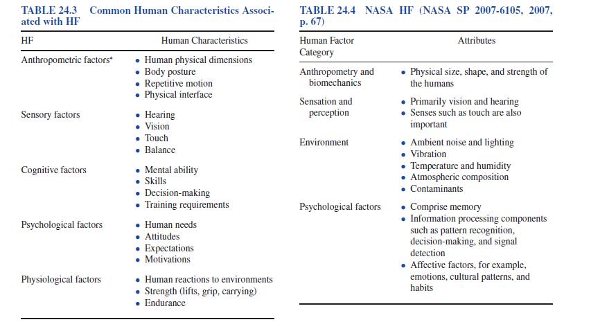
Compare and contrast the DoD CPAT and NASA HF perspectives listed in Tables 24.3 and 24.4. TABLE 24.3 Common Human Characteristics Associ- ated with HF HF Anthropometric factors* Sensory factors Cognitive factors Psychological factors Physiological factors Human Characteristics Human physical
What is an Engineering standard?
What is an Engineering convention?
Why do we need Engineering standards?
What are the key subject matter categories of Engineering standards?
What are some types of Engineering standards?
What are some types of conventions?
Who establishes Engineering standards at the global, national, professional, and Enterprise levels?
What are Enterprise standards and conventions?
What are some examples of Enterprise standards and conventions?
How is the degree of compliance with Engineering standards verified?
What is the difference between an Observer’s Frame of Reference and a Coordinate Reference System?
What are two conventions that apply to an Observer’s Frame of Reference?
Why is an Observer’s Frame of Reference convention is necessary but insufficient for defining a Coordinate Reference System.
What are the three possible multi-axis configurations for a Cartesian Coordinate Reference System?
How are Coordinate Reference Systems applied to A&D, medical, manufacturing, and business domains?Illustrate graphically.
What is an INS and how does it apply to a Body Frame of Reference Coordinate System?
What is the WCS and its two commonly used Earth models.
What is the Earth-Centered, Earth-Fixed (ECEF) model and how it is used?
What is the ECI model and how it is used?
What is the East-North-Up (ENU) and NED coordinate systems are, graphically explain their differences, and how they are used?
Why is application of the term “vertical” to some Coordinate Reference System configurations relative and how do you to deal with it?
What is a System’s 6-DoF?
What is themeaning, definition, and application of Euler Angles?
What is the meaning of a Free Body’s Yaw, Pitch, and Roll, their rotational conventions, and applications?
Why it is important to establish a project’s Standards of Units, Weights, Measures, and Coordinate Systems at the beginning of a project?
What is meant by a 6DOF’s translational and rotational movements?
Showing 1700 - 1800
of 5433
First
11
12
13
14
15
16
17
18
19
20
21
22
23
24
25
Last
Step by Step Answers