

Question: Derive the Boolean expression for the gate structure that clears the sequence counter SC to 0. Draw the logic diagram of the gates and show
Derive the Boolean expression for the gate structure that clears the sequence counter SC to 0. Draw the logic diagram of the gates and show how the output is connected to the INR and CLR inputs of SC (see Fig. 5-6). Minimize the number of gates.
Fig. 5-6
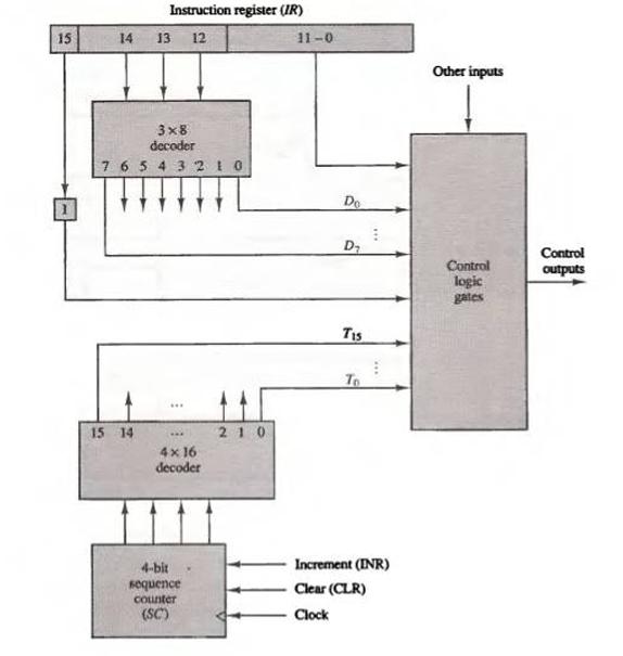
15 Instruction register (IR) 14 13 12 3x8 decoder 7 6 5 4 3 2 1 0 15 14 *** www 4x16 decoder 4-bit sequence counter (SC) 210 11-0 Do D T15 To Increment (INR) Clear (CLR) Clock Other inputs Control logic gates Control outputs
Step by Step Solution
3.46 Rating (159 Votes )
There are 3 Steps involved in it
The image you have provided shows a block diagram of a digital system with several components an Instruction Register IR decoders control logic gates ... View full answer

Get step-by-step solutions from verified subject matter experts