

Question: The position control system is shown in Fig. D9.3(a). The control parameters and variables are defined as Write state equations of the system and draw
The position control system is shown in Fig. D9.3(a). The control parameters and variables are defined as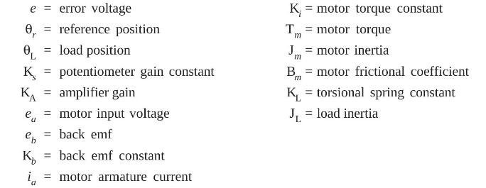
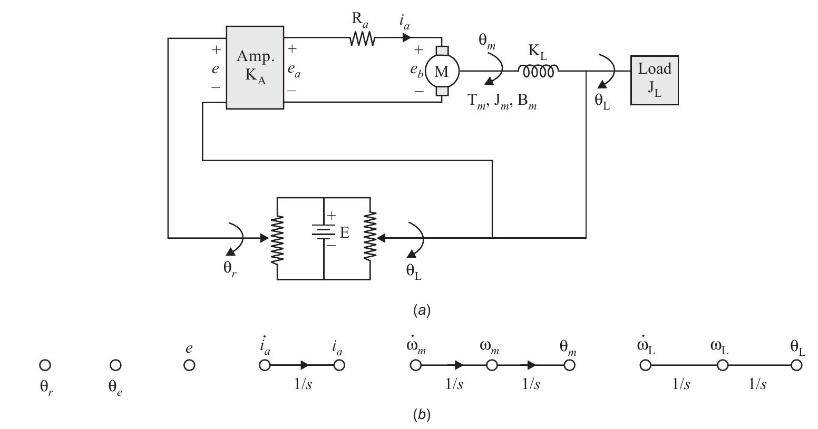
Write state equations of the system and draw state diagram (signal flow graph) using the nodes as shown in Fig. D9.3(b).
e 0 = reference position r OL = load position K = potentiometer gain constant KA = error voltage e = amplifier gain motor input voltage = back emf eb K i = motor armature current = back emf constant K = motor torque constant T = motor torque m J. motor inertia m B = motor frictional coefficient = KL JL = load inertia = torsional spring constant
Step by Step Solution
There are 3 Steps involved in it
The provided figures show a position control system along with the definitions of various control parameters and variables To write the state equation... View full answer

Get step-by-step solutions from verified subject matter experts