

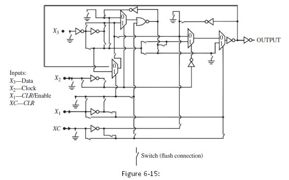
(a) Indicate the connections of the switches in Figure 6-15 to realize the function F = AB...
Question:
F = AB + A€™C
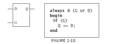
(b) Indicate the connections of the switches in Figure 6-15 to realize a latch as shown in Figure 2-18.
(c) Indicate the connections of the switches in Figure 6-15 to realize a D-flip-flop.
Fantastic news! We've Found the answer you've been seeking!
Step by Step Answer:
a b c B A D...View the full answer

Answered By
Susan Juma
I'm available and reachable 24/7. I have high experience in helping students with their assignments, proposals, and dissertations. Most importantly, I'm a professional accountant and I can handle all kinds of accounting and finance problems.
15+ Reviews
45+ Question Solved
Related Book For 
Digital Systems Design Using Verilog
ISBN: 978-1285051079
1st edition
Authors: Charles Roth, Lizy K. John, Byeong Kil Lee
Question Posted:
