

Question: Design a 4 Ã 4 keypad scanner for the following keypad layout. (a) Assuming only one key can be pressed at a time, find the
Design a 4 × 4 keypad scanner for the following keypad layout.
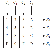
(a) Assuming only one key can be pressed at a time, find the equations for a number decoder given R3-0 and C3-0, whose output corresponds to the binary value of the key. For example, the F key will return N3-0 = 1111 in binary, or 15.
(b) Design a debouncing circuit that detects when a key has been pressed or depressed. Assume switch bounce will die out in one or two clock cycles. When a key has been pressed, K = 1 and Kd is the debounced signal.
(c) Design and draw a state graph that performs the keyscan and issues a valid pulse when a valid key has been pressed using inputs from part (b).
(d) Write a Verilog description of your keypad scanner and include the decoder, the debouncing circuit, and the scanner.
C C2 C3 Ro 3 A - R1 4 5 6. B -R2 R3 2.
Step by Step Solution
3.36 Rating (168 Votes )
There are 3 Steps involved in it
a Truth table and resulting equations acquired used a CAD program such as LogicAid Logic equations f... View full answer

Get step-by-step solutions from verified subject matter experts