

Question: Implement the following state table using a ROM and two D flip-flops. Use a straight binary state assignment. (a) Show the block diagram and the
(a) Show the block diagram and the ROM truth table. Truth table column headings should be in the order Q1 Q0 X D1 D0 Z.
(b) Write Verilog code for the implementation. Use an array to represent the ROM table, and use two processes.
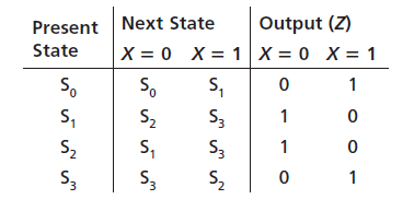
Next State Output (Z) Present State X = 0 X = 1 X = 0 X= 1 So S, So S2 S, S2 S3 S3 S3 S3 S2
Step by Step Solution
★★★★★
3.27 Rating (162 Votes )
There are 3 Steps involved in it
1 Expert Approved Answer
Step: 1 Unlock

a b module ROMQ3X Clk Z input X Clk output reg Z reg 10 Q Qplus reg 20 FSMR... View full answer
Question Has Been Solved by an Expert!
Get step-by-step solutions from verified subject matter experts
Step: 2 Unlock
Step: 3 Unlock