

Question: The following state table is implemented using a ROM and two D flip-flops (falling edge triggered): (a) Draw the block diagram. (b) Write Verilog code
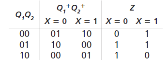
(a) Draw the block diagram.
(b) Write Verilog code that describes the system. Assume that the ROM has a delay of 10ns and each flip-flop has a propagation delay of 15ns.
Q,+Q,* X = 0 X = 1 Q,Q2 X = 0 X = 1 00 01 10 01 10 00 10 00 01 1
Step by Step Solution
★★★★★
3.53 Rating (160 Votes )
There are 3 Steps involved in it
1 Expert Approved Answer
Step: 1 Unlock

a b module ROMQ4X Clk Z input X Clk output reg Z reg 12 Q Qplus reg 20 FSMROM ... View full answer
Question Has Been Solved by an Expert!
Get step-by-step solutions from verified subject matter experts
Step: 2 Unlock
Step: 3 Unlock