

Consider the circuit of Figure 4-41. Output Y is supposed to go HIGH for either of the
Question:
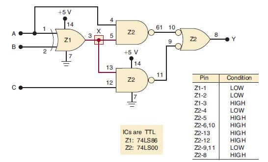
Consider the circuit of Figure 4-41. Output Y is supposed to go HIGH for either of the following conditions:
1. A = 1, B = 0 regardless of the level on C
2. A = 0, B = 1, C = 1
You may wish to verify these results for yourself.
When the circuit is tested, the technician observes that output Y goes HIGH whenever A is HIGH or C is HIGH, regardless of the level at B. She takes logic probe measurements for the condition where A = B = 0, C = 1 and comes up with the indications recorded in Figure 4-41.
Examine the recorded levels and list the possible causes for the malfunction. Then develop a step-by-step procedure to determine the exact fault.
Figure 4-41
Fantastic news! We've Found the answer you've been seeking!
Step by Step Answer:
All of the NAND gate outputs are correct for the levels present at their inputs The XOR gate however should be producing a LOW at output pin 3 because ...View the full answer

Answered By
Rishabh Ojha
During my undergraduate i used to participate as TA (Teaching Assistant) in several electronics and computers subject. I'm passionate about learning Computer Science as my bachelors are in Electronics but i learnt most of the Computer Science subjects on my own which Machine Learning also. At Present, i'm a working professional pursuing my career as a Machine Learning Engineer and i want to help others learn during my free hours, that's all the motivation behind giving tuition. To be frank i have no prior experience of tutoring but i have solved problems on opensource platforms like StackOverflow and github. ~Thanks
3+ Reviews
10+ Question Solved
Related Book For 

Digital Systems Principles And Application
ISBN: 9780134220130
12th Edition
Authors: Ronald Tocci, Neal Widmer, Gregory Moss
Question Posted:
