The circuit shown in Figure P26 consists of a resistor and a capacitor and is thus called
Question:
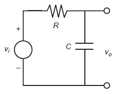
The circuit shown in Figure P26 consists of a resistor and a capacitor and is thus called an RC circuit. If we apply a sinusoidal voltage υi, called the input voltage, to the circuit as shown, then eventually the output voltage !o will be sinusoidal also, with the same frequency but with a different amplitude and shifted in time relative to the input voltage. Specifically , if υi = Ai sin (t, then υo = Ao sin(ωt + ϕ). The frequency–response plot is a plot of Ao /Ai versus frequency ω. It is usually plotted on logarithmic axes.
Upper-level engineering courses explain that for the RC circuit shown, this ratio depends on ω and RC as follows:
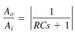
where s = ωi. For RC = 0.1 s, obtain the log-log plot of versus ω and use it to find the range of frequencies for which the output amplitude Ao is less than 70 percent of the input amplitude Ai.
Figure P26
Step by Step Answer:
ANSWER First we need to obtain the frequencyresponse function by substit...View the full answer