

Question: Do an automatic logic simulation- based verification of your design in Problem 4-14. The input sequence used in the simulation should include all transitions in
Do an automatic logic simulation- based verification of your design in Problem 4-14. The input sequence used in the simulation should include all transitions in Figure 4-50. The simulation output should include the input X and the state variables A, B, and output Z.
Problem 4-14:
The state diagram for a sequential circuit appears in Figure 4-50.
Figure 4-50:
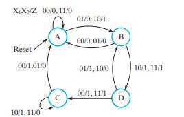
XX/Z 00/0, 11/0 Reset 00/1,01/0 10/1, 11/0 A 01/0, 10/1 00/0, 01/0 01/1, 10/0 00/1, 11/1 B D 10/1, 11/1
Step by Step Solution
3.52 Rating (152 Votes )
There are 3 Steps involved in it
It appears youre referring to a state diagram and asking for a logic simulation based verification of a sequential circuit design Unfortunately since ... View full answer

Get step-by-step solutions from verified subject matter experts